sh030106u.pdf - 第139页
4. STA RTUP 4 - 14 4.4 Test operatio n Before starti ng actual operation, p erform tes t operatio n to mak e s ure that the ma chine operates normal ly. Refer to sectio n 4.2 for t he power o n and off m ethods of the s …
4. STARTUP
4 - 13
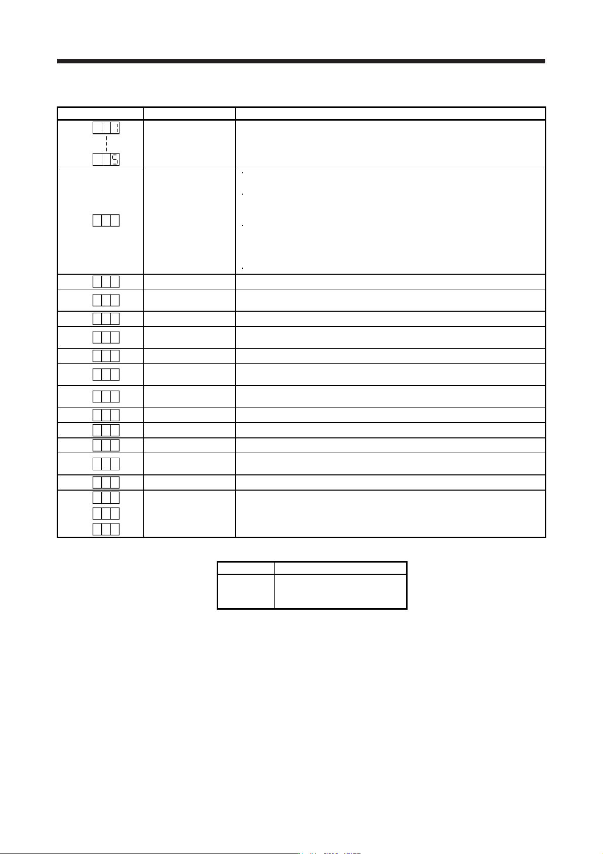
(2) Indication list
Indication Status Description
Initializing System check in progress
A b
Initializing
Power of the servo amplifier was switched on at the condition that the power of the
servo system controller is off.
The control axis No. set to the auxiliary axis number setting switches (SW2-3 and
SW2-4) and the axis selection rotary switch (SW1) do not match the one set to the
servo system controller.
A servo amplifier malfunctioned, or communication error occurred with the servo
system controller or the previous axis servo amplifier. In this case, the indication
changes as follows:
"Ab", "AC", "Ad", and "Ab"
The servo system controller is malfunctioning.
A b .
Initializing During initial setting for communication specifications
A C
Initializing
Initial setting for communication specifications completed, and then it synchronized
with servo system controller.
A d
Initializing During initial parameter setting communication with servo system controller
A E
Initializing
During the servo motor/encoder information and telecommunication with servo
system controller
A F
Initializing During initial signal data communication with servo system controller
A H
Initializing completion
The process for initial data communication with the servo system controller is
completed.
A A
Initializing standby
The power supply of servo system controller is turned off during the power supply of
servo amplifier is on.
(Note 1)
b
# #
Ready-off The ready-off signal from the servo system controller was received.
(Note 1)
d
# #
Servo-on The ready-off signal from the servo system controller was received.
(Note 1)
C
# #
Servo-off The ready-off signal from the servo system controller was received.
(Note 2)
* **
Alarm and warning
The alarm No. and the warning No. that occurred is displayed. (Refer to section 8.
(Note 4))
8 88
CPU error CPU watchdog error has occurred.
(Note 1)
# #b.
(Note 3)
Test operation mode
JOG operation, positioning operation, program operation, output signal (DO) forced
output, or motor-less operation was set.
# #d.
# #C.
Note 1. The meanin
g
s of ## are listed below.
## Description
01
to
64
Axis No. 1
to
Axis No. 64
2. ** indicates the alarm No. and the warnin
g
No.
3. Requires the MR Confi
g
urator2.
4. Only a list of alarms and warnings is listed in chapter 8. Refer to "MELSERVO-J4 Servo Amplifier Instruction Manual
(
Troubleshootin
g)
" for details of alarms and warnin
g
s.
4. STARTUP
4 - 14
4.4 Test operation
Before starting actual operation, perform test operation to make sure that the machine operates normally.
Refer to section 4.2 for the power on and off methods of the servo amplifier.
POINT
If necessary, verify controller program by using motor-less operation. Refer to
section 4.5.2 for the motor-less operation.
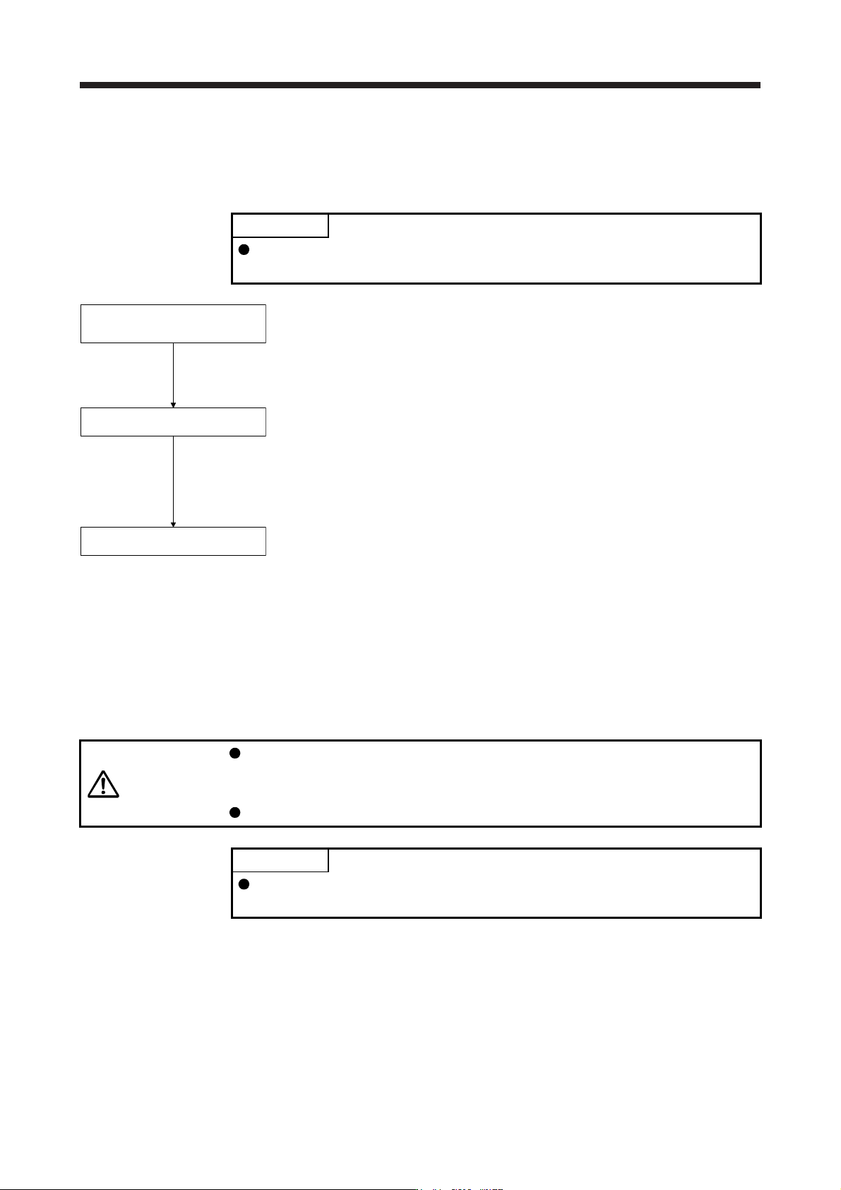
Test operation of the servo motor
alone in JOG operation of test
operation mode
Test operation of the servo motor
alone by commands
Test operation with the servo motor
and machine connected
In this step, confirm that the servo amplifier and servo motor operate
normally. With the servo motor disconnected from the machine, use the test
operation mode and check whether the servo motor rotates correctly. Refer
to section 4.5 for the test operation mode.
In this step, confirm that the servo motor rotates correctly under the
commands from the controller.
Give a low speed command at first and check the rotation direction, etc. of
the servo motor. If the machine does not operate in the intended direction,
check the input signal.
In this step, connect the servo motor with the machine and confirm that the
machine operates normally under the commands from the controller.
Give a low speed command at first and check the operation direction, etc. of
the machine. If the machine does not operate in the intended direction,
check the input signal.
Check any problems with the servo motor speed, load ratio, and other status
display items with MR Configurator2.
Then, check automatic operation with the program of the controller.
4.5 Test operation mode
CAUTION
The test operation mode is designed for checking servo operation. It is not for
checking machine operation. Do not use this mode with the machine. Always use
the servo motor alone.
If the servo motor operates abnormally, use EM2 (Forced stop 2) to stop it.
POINT
The content described in this section indicates that the servo amplifier and a
personal computer are directly connected.
By using a personal computer and MR Configurator2, you can execute jog operation, positioning operation,
output signal (DO) forced output program operation without connecting the servo system controller.
4. STARTUP
4 - 15
4.5.1 Test operation mode in MR Configurator2
POINT
When the test operation mode is selected with the test operation select switch
(SW2-1), the SSCNET III/H communication for the servo amplifier in the test
operation mode and the following servo amplifiers is blocked.
(1) Test operation mode
(a) Jog operation
Jog operation can be performed without using the servo system controller. Use this operation with
the forced stop reset. This operation may be used independently of whether the servo is on or off
and whether the servo system controller is connected or not.
Exercise control on the jog operation screen of MR Configurator2.
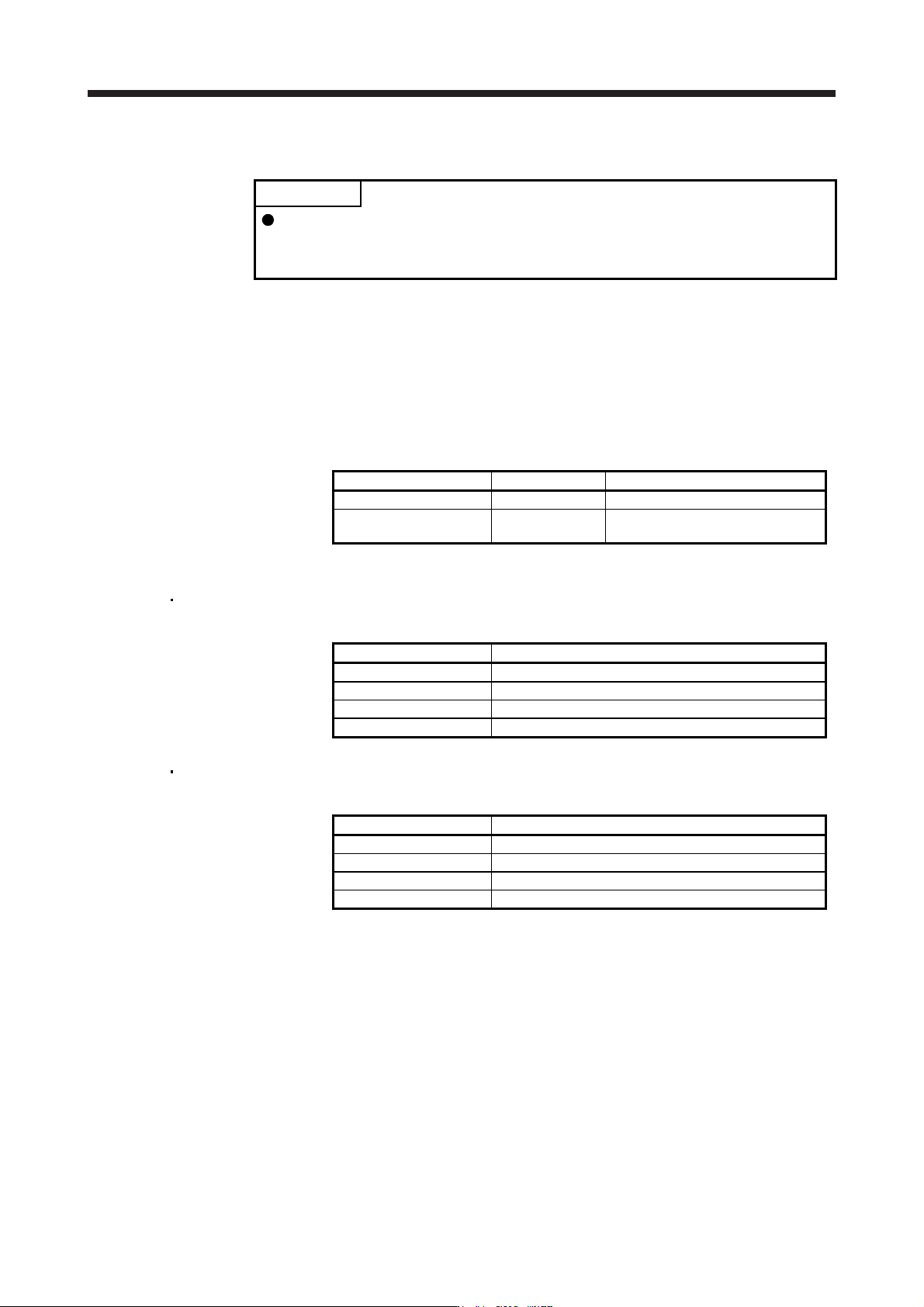
1) Operation pattern
Item initial value Setting range
Speed [r/min] 200 0 to max. speed
Acceleration/deceleration
time constant [ms]
1000 0 to 50000
2) Operation method
When the check box of "Rotation only while the CCW or CW button is being pushed." is
checked.
Operation Screen control
Forward rotation start Keep pressing "Forward".
Reverse rotation start Keep pressing "Reverse".
Stop Release "Forward" or "Reverse".
Forced stop Click "Forced stop".
When the check box of "Rotation only while the CCW or CW button is being pushed." is not
checked.
Operation Screen control
Forward rotation start Click "Forward".
Reverse rotation start Click "Reverse".
Stop Click "Stop".
Forced stop Click "Forced stop".