sh030106u.pdf - 第433页
11. OPT I ONS AND PER IPH ERA L EQU IPM ENT 11 - 11 2 (b) DBU-11 K-4/D BU-22K-4 [Unit: mm] 15 51 25 15 73.75 7 25 150 10 200 170 178.5 179.5 15 260 280 43 10 2- φ 7 mounting hole 195 228 26 26 210 2.3 Mass: 6.7 [kg] Term…
11. OPTIONS AND PERIPHERAL EQUIPMENT
11 - 111
(4) Dim
ensions
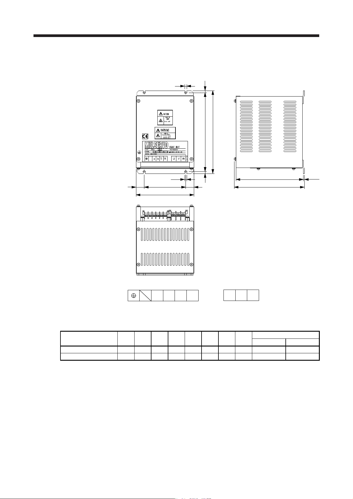
(a) DBU-11K/DBU-15K/DBU-22K-R1
[Unit: mm]
C
D 100 D
5
E EB
A
5
F
2.3G
ab13
Terminal block
14
Screw: M3.5
Tightening torque: 0.8 [N•m]
UVW
Screw: M4
Tighteni
ng torque: 1.2 [N•m]
External dynamic brake A B C D E F G
Mass
[kg
]
(Note) Connection wire [mm
2
]
U/V/W Except U/V/W
DBU-11K 200 190 140 20 5 170 163.5 2 5.5 (AWG 10) 2 (AWG 14)
DBU-15K/DBU-22K-R1 250 238 150 25 6 235 228 6 5.5 (AWG 10) 2 (AWG 14)
Note. Selection conditions of wire size are as follows.
600 V grade heat-resistant polyvinyl chloride insulated wire (HIV wire)
Construction condition: Sin
g
le wire set in midai
r
11. OPTIONS AND PERIPHERAL EQUIPMENT
11 - 112
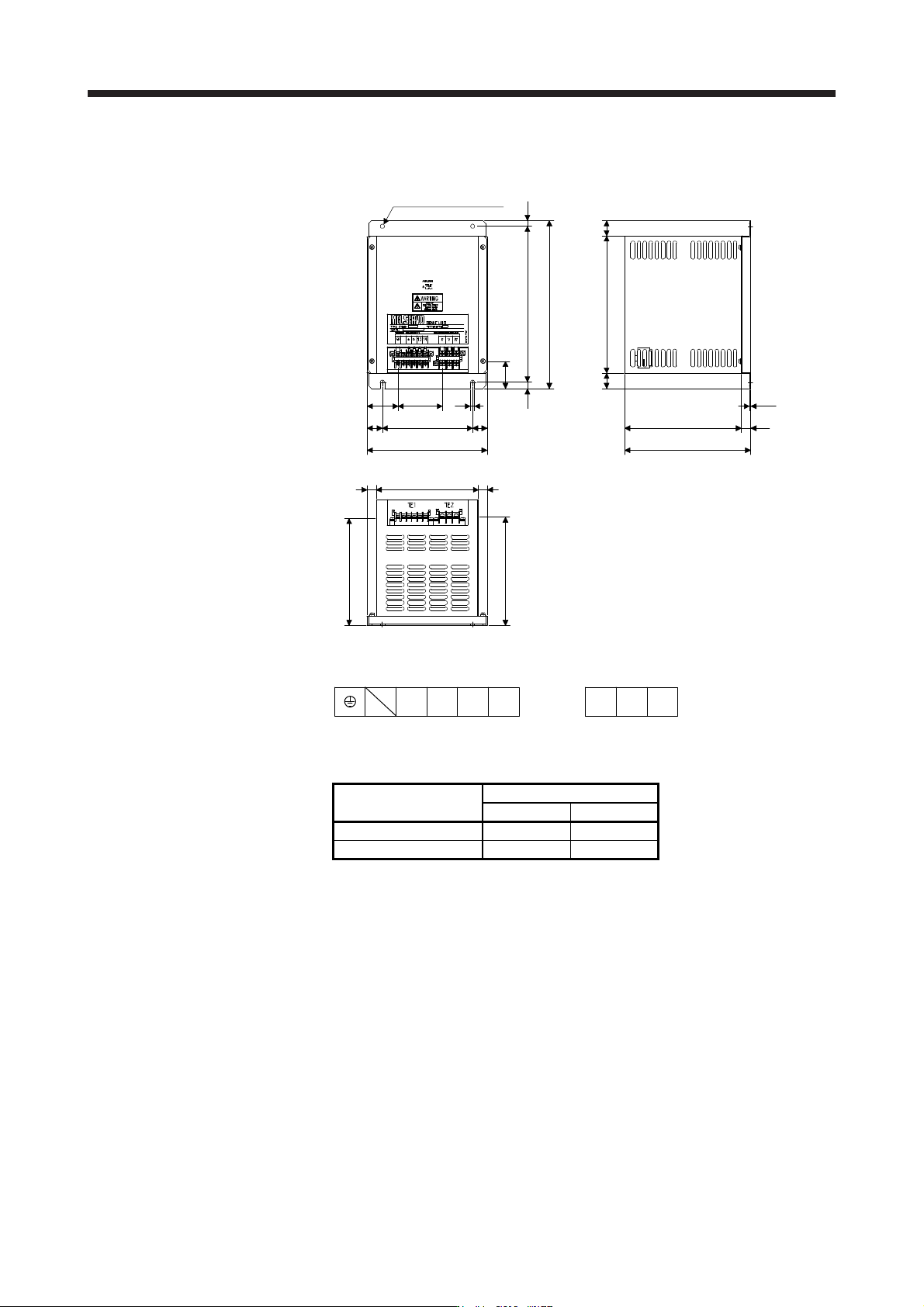
(b) DBU-11K-4/D
BU-22K-4
[Unit: mm]
15
51
25
15
73.75 7
25150
10
200
170
178.5
179.5
15
260
280
43
10
2-φ7 mounting hole
195
228
2626
210
2.3
Mass: 6.7 [kg]
Terminal block
TE1
a b 13 14
Screw: M3.5
Tightening torque: 0.8 [N•m]
TE2
WVU
Screw: M4
Tightening torque: 1.2 [N•m]
External dynamic brake
(Note) C
onnection wire [mm
2
]
U/V/W Except U/V/W
DBU-11K-4 5.5 (AWG 10) 2 (AWG 14)
DBU-22K-4 5.5 (AWG 10) 2 (AWG 14)
Note. Selection conditions of wire size are as follows.
Wire type: 600 V grade heat-resistant polyvinyl chloride insulated wire (HIV wire)
Construction condition: Sin
g
le wire set in midai
r
11. OPTIONS AND PERIPHERAL EQUIPMENT
11 - 113
11.18 P
anel through attachment (MR-J4ACN15K/MR-J3ACN)
Use the panel through attachment to mount the heat generation area of the servo amplifier in the outside of
the cabinet to dissipate servo amplifier-generated heat to the outside of the cabinet and reduce the amount
of heat generated in the cabinet. In addition, designing a compact cabinet is allowed.
In the cabinet, machine a hole having the panel cut dimensions, fit the panel through attachment to the servo
amplifier with the fitting screws (4 screws supplied), and install the servo amplifier to the cabinet.
Please prepare screws for mounting. They do not come with.
The environment outside the cabinet when using the panel through attachment should be within the range of
the servo amplifier operating environment.
The panel through attachments are used for MR-J4-11KB(-RJ) to MR-J4-22KB(-RJ) and MR-J4-11KB4(-RJ)
to MR-J4-22KB4(-RJ).
The following shows the combinations.
Servo amplifier Panel through attachment
MR-J4-11KB(-RJ)
MR-J4-15KB(-RJ)
MR-J4ACN15K
MR-J4-22KB(-RJ) MR-J3ACN
MR-J4-11KB4(-RJ)
MR-J4-15KB4(-RJ)
MR-J4ACN15K
MR-J4-22KB4(-RJ) MR-J3ACN
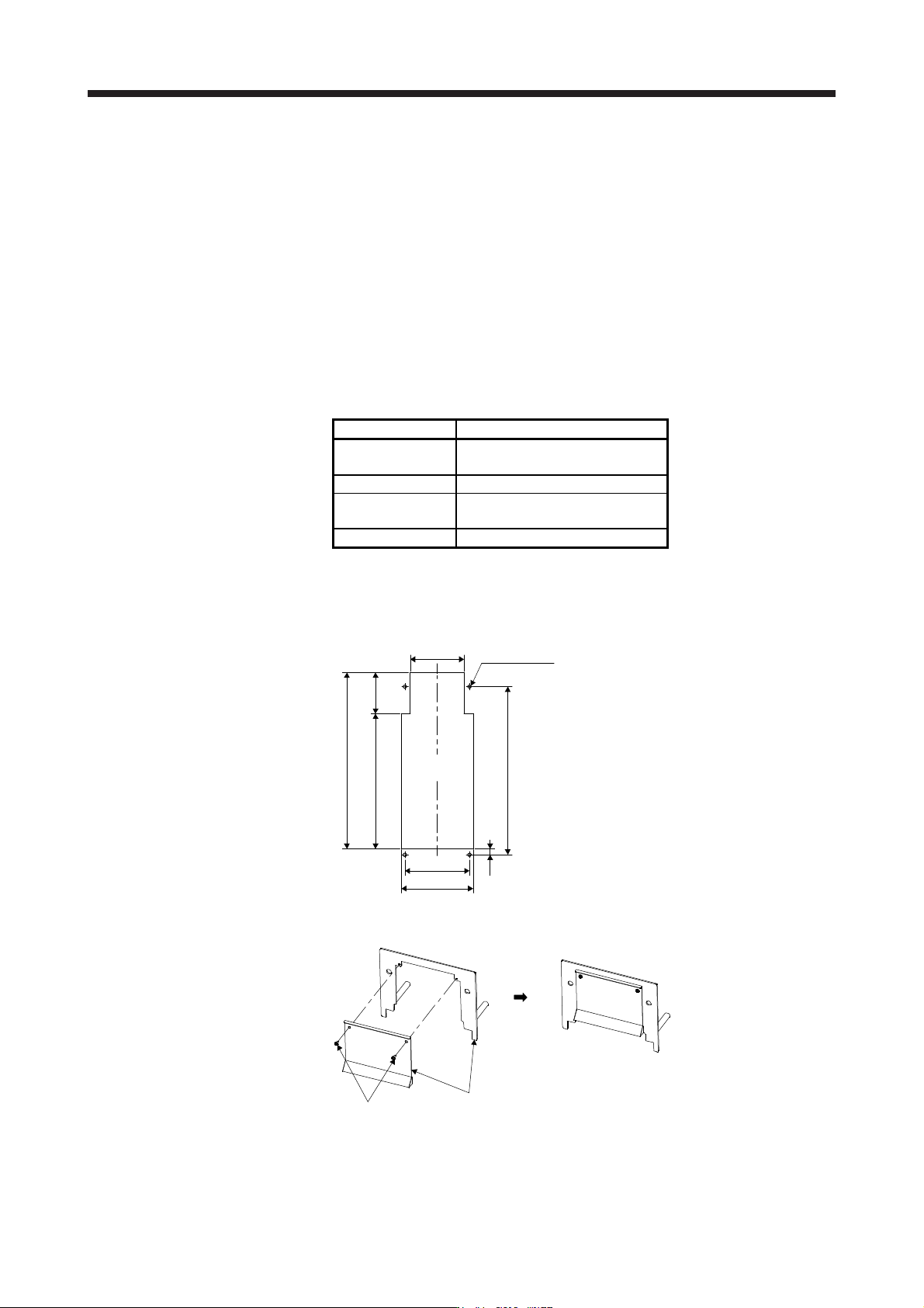
(1) MR
-J4ACN15K
(a) Panel cut dimensions
[Unit: mm]
196
218
18
510
410
535
Approx.
125
163
4-M10 Screw
Punched
hole
(b) How to as
semble the attachment for panel through attachment
Screw
(2 places)
Attachment