sh030106u.pdf - 第399页
11. OPT ION S AND P ERI PHER AL EQU IPMENT 11 - 78 11.11 Power factor i mprovi ng DC reactor s The foll owing sho ws the ad vantag es of us ing power factor improv ing DC r eactor. It improves th e power facto r by inc r…
11. OPTIONS AND PERIPHERAL EQUIPMENT
11 - 77
The Type E Combination motor controller can also be used instead of a molded-case circuit breaker.
Servo amplifier
Rated input
voltage AC [V]
Input phase
Type E Combination motor controller
SCCR
[kA]
Model
Rated
voltage
AC [V]
Rated current
[A]
(Heater design)
MR-J4-10B(-RJ)
200 to 240 3-phase
MMP-T32
240
1.6
50
MR-J4-20B(-RJ) 2.5
MR-J4-40B(-RJ) 4
MR-J4-60B(-RJ) 6.3
MR-J4-70B(-RJ) 6.3
MR-J4-100B(-RJ) 8
MR-J4-200B(-RJ) 18
MR-J4-350B(-RJ) 25
25
MR-J4-500B(-RJ) 32
MR-J4-60B4(-RJ)
380 to 480 3-phase 480Y/277
2.5
50
MR-J4-100B4(-RJ) 4
MR-J4-200B4(-RJ) 8
MR-J4-350B4(-RJ) 13
MR-J4-500B4(-RJ) 18
MR-J4-700B4(-RJ) 25 25
(2) For control circuit power supply
When the wiring for the control circuit power supply (L11/L21) is thinner than that for the main circuit
power supply (L1/L2/L3), install an overcurrent protection device (molded-case circuit breaker or fuse) to
protect the branch circuit.
Servo amplifier
Molded-case circuit breaker (Note) Fuse (Class T) Fuse (Class K5)
Frame, rated current Voltage AC [V] Current [A] Voltage AC [V] Current [A] Voltage AC [V]
MR-J4-10B(-RJ)
MR-J4-20B(-RJ)
MR-J4-40B(-RJ)
MR-J4-60B(-RJ)
MR-J4-70B(-RJ)
MR-J4-100B(-RJ)
MR-J4-200B(-RJ) 30 A frame 5 A 240 1 300 1 250
MR-J4-350B(-RJ)
MR-J4-500B(-RJ)
MR-J4-700B(-RJ)
MR-J4-11KB(-RJ)
MR-J4-15KB(-RJ)
MR-J4-22KB(-RJ)
MR-J4-60B4(-RJ)
MR-J4-100B4(-RJ)
MR-J4-200B4(-RJ)
MR-J4-350B4(-RJ)
MR-J4-500B4(-RJ) 30 A frame 5 A 480 1 600 1 600
MR-J4-700B4(-RJ)
MR-J4-11KB4(-RJ)
MR-J4-15KB4(-RJ)
MR-J4-22KB4(-RJ)
MR-J4-10B1(-RJ)
MR-J4-20B1(-RJ) 30 A frame 5 A 240 1 300 1 250
MR-J4-40B1(-RJ)
Note. When havin
g
the servo amplifier compl
y
with the IEC/EN/UL/CSA standard, refer to app. 4.
11. OPTIONS AND PERIPHERAL EQUIPMENT
11 - 78
11.11 Power factor improving DC reactors
The following shows the advantages of using power factor improving DC reactor.
It improves the power factor by increasing the form factor of the servo amplifier's input current.
It decreases the power supply capacity.
The input power factor is improved to about 85%.
As compared to the power factor improving AC reactor (FR-HAL-(H)), it decreases the loss.
When connecting the power factor improving DC reactor to the servo amplifier, always disconnect P3 and
P4. If it remains connected, the effect of the power factor improving DC reactor is not produced.
When used, the power factor improving DC reactor generates heat. To release heat, therefore, leave a 10
cm or more clearance at each of the top and bottom, and a 5 cm or more clearance on each side.
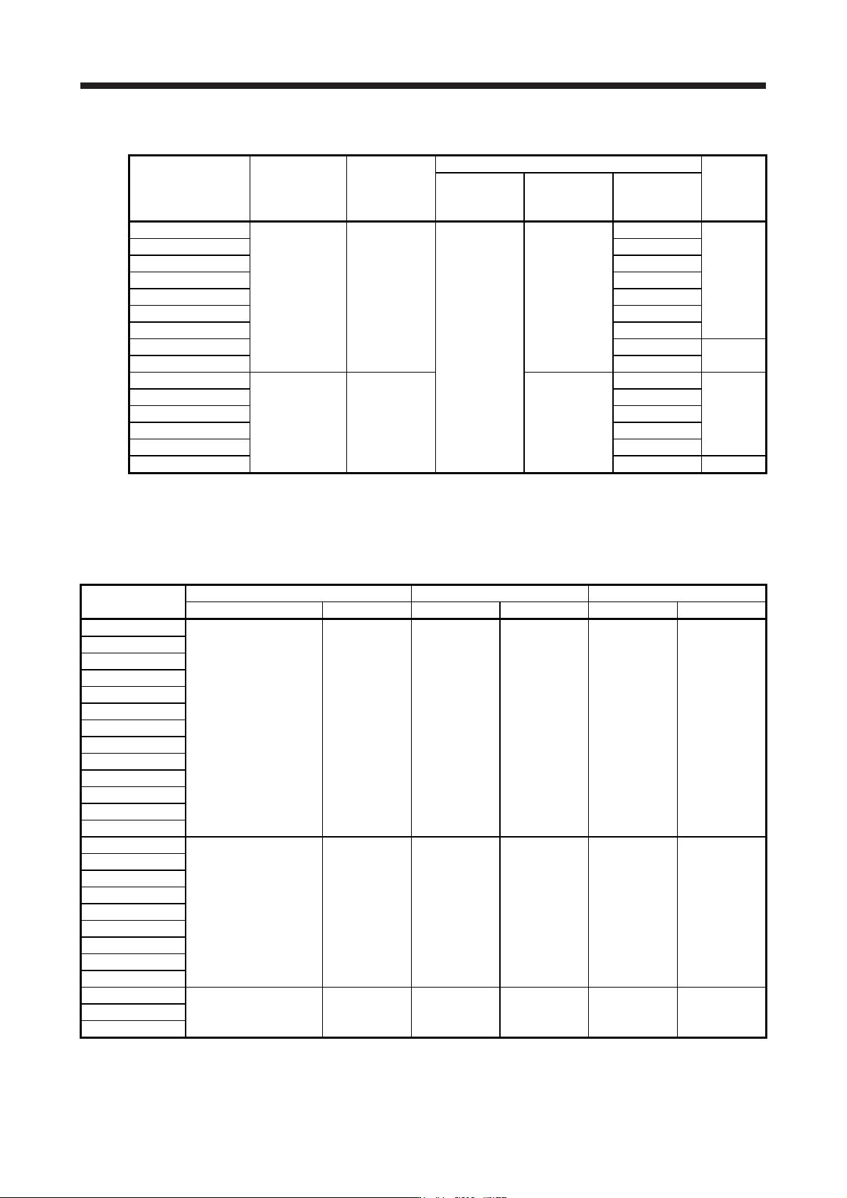
(1) 200 V class
2-d mounting hole
(Varnish is removed from right mounting
hole (face and back side).) (Note 1)
D or less
W ± 2
W1
H
PP1
Fig. 11.1
4-d mounting hole
(Varnish is removed from front right mounting
hole (face and back side).) (Note 1)
D or less
W ± 2
W1
H
D1
D3
D2
PP1
Fig. 11.2
D or less
D3 or less
W ± 2
W1
D1 ± 2
D2
H ± 2
4-d mounting hole (Note 1)
P1
P
Fig. 11.3
(Note 2)
Servo amplifier
P3
P4
FR-HEL
5 m or less
P1
P
Note 1. Use this for
g
roundin
g
.
2. When usin
g
the power factor improvin
g
DC reactor, remove the short bar across P3 and P4.
11. OPTIONS AND PERIPHERAL EQUIPMENT
11 - 79
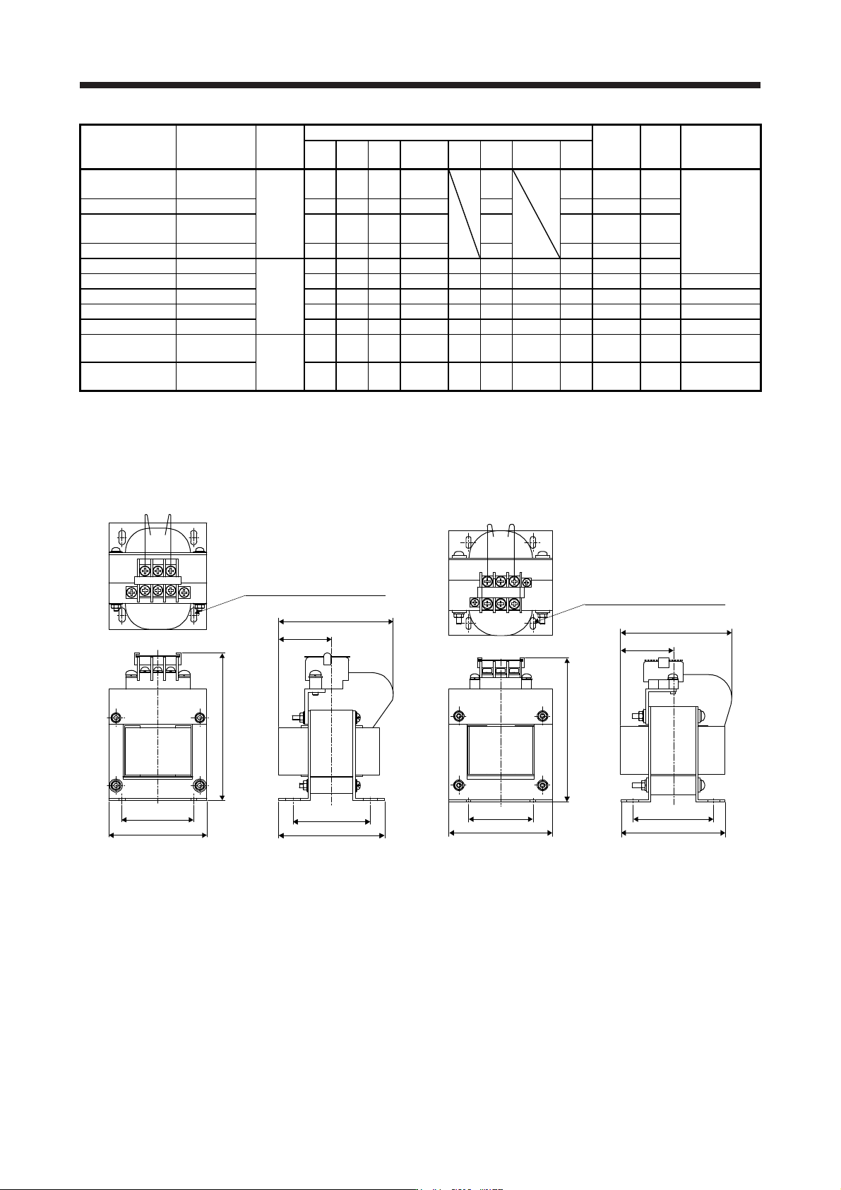
Servo amplifier
Power factor
improving DC
reactor
Dimensions
Dimensions [mm]
Terminal
size
Mass
[kg]
Wire [mm
2
]
(Note 2)
W W1 H
D
(Note 1)
D1 D2 D3 d
MR-J4-10B(-RJ)
MR-J4-20B(-RJ)
FR-HEL-0.4K
Fig. 11.1
70 60 71 61
21
M4 M4 0.4
2 (AWG 14)
MR-J4-40B(-RJ) FR-HEL-0.75K 85 74 81 61 21 M4 M4 0.5
MR-J4-60B(-RJ)
MR-J4-70B(-RJ)
FR-HEL-1.5K 85 74 81 70 30 M4 M4 0.8
MR-J4-100B(-RJ) FR-HEL-2.2K 85 74 81 70 30 M4 M4 0.9
MR-J4-200B(-RJ) FR-HEL-3.7K
Fig. 11.2
77 55 92 82 66 57 37 M4 M4 1.5
MR-J4-350B(-RJ) FR-HEL-7.5K 86 60 113 98 81 72 43 M4 M5 2.5 3.5 (AWG 12)
MR-J4-500B(-RJ) FR-HEL-11K 105 64 133 112 92 79 47 M6 M6 3.3 5.5 (AWG 10)
MR-J4-700B(-RJ) FR-HEL-15K 105 64 133 115 97 84 48.5 M6 M6 4.1 8 (AWG 8)
MR-J4-11KB(-RJ) FR-HEL-15K 105 64 133 115 97 84 48.5 M6 M6 4.1 14 (AWG 6)
MR-J4-15KB(-RJ) FR-HEL-22K
Fig. 11.3
105 64 93 175 117 104
115
(Note 1)
M6 M10 5.6 22 (AWG 4)
MR-J4-22KB(-RJ) FR-HEL-30K 114 72 100 200 125 101
135
(Note 1)
M6 M10 7.8 38 (AWG 2)
Note 1. Maximum dimensions The dimension varies dependin
g
on the input/output lines.
2. Selection conditions of wire size are as follows.
600 V grade heat-resistant polyvinyl chloride insulated wire (HIV wire)
Construction condition: Sin
g
le wire set in midai
r
(2) 400 V class
W1
D2
W ± 2.5
H ± 2.5
D or less
(D3)
D1 ± 1
4-d mounting hole (Note 1)
PP1
Fig. 11.4
W1
W ± 2.5
D2
D1 ± 1
H ± 2.5
PP1
D or less
(D3)
4-d mounting hole (Note 1)
Fig. 11.5