sh030106u.pdf - 第602页
17. APPLICATIO N OF FUNCTIONS 17 - 51 2) Switchab le gain par amet er Loop gain Before swi tching After switching Parameter Symbol Name Paramet er S ymbol Name Load to motor inertia ratio/l oad to motor mass ratio PB06 G…
17. APPLICATION OF FUNCTIONS
17 - 50
(c) Parameter
When using the gain switching function, always select "Manual mode (_ _ _ 3)" of "Gain adjustment
mode selection" in [Pr. PA08 Auto tuning mode]. The gain switching function cannot be used in the
auto tuning mode.
1) Parameter for setting gain switching condition
Parameter Symbol Name Unit Description
PB26 CDP Gain switching function Select a switching condition.
PB27 CDL Gain switching condition [kpulse/s]
/[pulse]
/[r/min]
Set a switching condition values.
PB28 CDT Gain switching time constant [ms] Set the filter time constant for a gain change at switching.
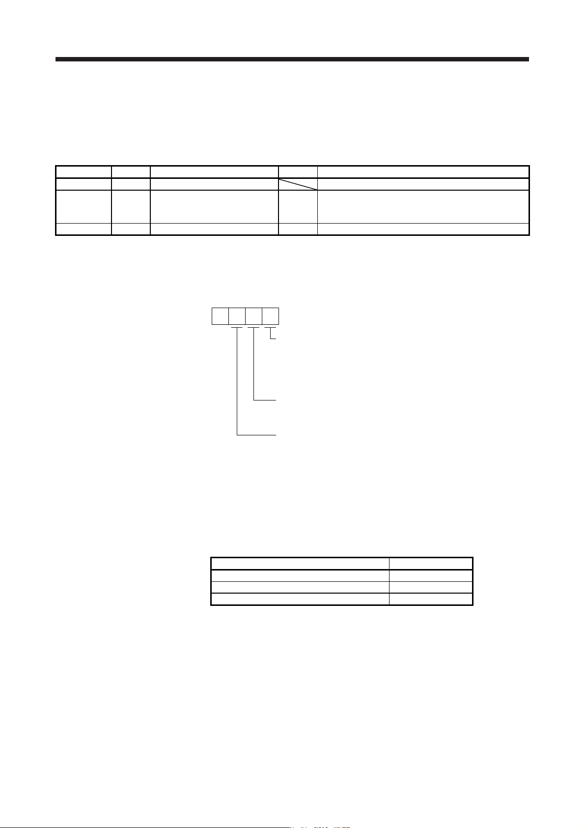
a) [Pr. PB26 Gain switching function]
Used to set the gain switching condition. Select the switching condition in the first to third
digits.
Gain switching selection
0: Disabled
1: Control command from controller is enabled
2: Command frequency
3: Droop pulses
4: Servo motor speed/linear servo motor speed
0
Gain switching condition
0: Gain after switching is enabled with gain switching condition or mor
e
1: Gain after switching is enabled with gain switching condition or less
[Pr. PB26]
Gain switching time constant disabling condition selection
0: Switching time constant enabled
1: Switching time constant disabled
2: Return time constant disabled
b) [Pr. PB27 Gain switching condition]
Set a level to switch gains with [Pr. PB27] after you select "Command frequency", "Droop
pulses", or "Servo motor speed/linear servo motor speed" with the gain switching selection in
[Pr. PB26 Gain switching function].
The setting unit is as follows.
Gain switching condition Unit
Command frequency [kpulse/s]
Droop pulses [pulse]
Servo motor speed/linear servo motor speed [r/min]/[mm/s]
c) [Pr. PB28 Gain switching time constant]
You can set the primary delay filter to each gain at gain switching. This parameter is used to
suppress shock given to the machine if the gain difference is large at gain switching, for
example.
17. APPLICATION OF FUNCTIONS
17 - 51
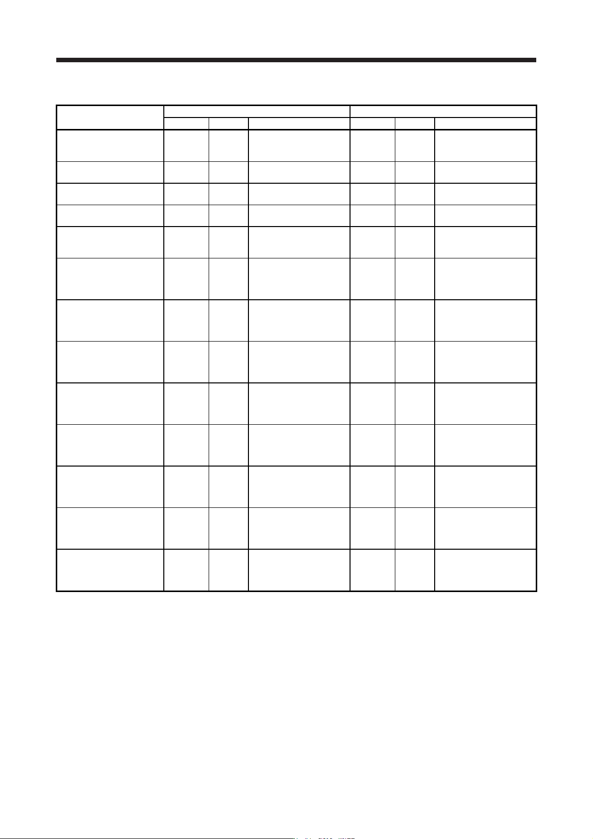
2) Switchable gain parameter
Loop gain
Before switching After switching
Parameter Symbol Name Parameter Symbol Name
Load to motor inertia
ratio/load to motor mass
ratio
PB06 GD2
Load to motor inertia
ratio/load to motor mass
ratio
PB29 GD2B
Load to motor inertia
ratio/load to motor mass
ratio after gain switching
Model loop gain PB07 PG1 Model loop gain PX12 PG1B
Model loop gain after gain
switching
Position loop gain PB08 PG2 Position loop gain PB30 PG2B
Position loop gain after
gain switching
Speed loop gain PB09 VG2 Speed loop gain PB31 VG2B
Speed loop gain after gain
switching
Speed integral
compensation
PB10 VIC
Speed integral
compensation
PB32 VICB
Speed integral
compensation after gain
switching
Vibration suppression
control 1 - Vibration
frequency
PB19 VRF11
Vibration suppression
control 1 - Vibration
frequency
PB33 VRF11B
Vibration suppression
control 1 - Vibration
frequency after gain
switching
Vibration suppression
control 1 - Resonance
frequency
PB20 VRF12
Vibration suppression
control 1 - Resonance
frequency
PB34 VRF12B
Vibration suppression
control 1 - Resonance
frequency after gain
switching
Vibration suppression
control 1 - Vibration
frequency damping
PB21 VRF13
Vibration suppression
control 1 - Vibration
frequency damping
PB35 VRF13B
Vibration suppression
control 1 - Vibration
frequency damping after
gain switching
Vibration suppression
control 1 - Resonance
frequency damping
PB22 VRF14
Vibration suppression
control 1 - Resonance
frequency damping
PB36 VRF14B
Vibration suppression
control 1 - Resonance
frequency damping after
gain switching
Vibration suppression
control 2 - Vibration
frequency
PX04 VRF21
Vibration suppression
control 2 - Vibration
frequency
PX08 VRF21B
Vibration suppression
control 2 - Vibration
frequency after gain
switching
Vibration suppression
control 2 - Resonance
frequency
PX05 VRF22
Vibration suppression
control 2 - Resonance
frequency
PX09 VRF22B
Vibration suppression
control 2 - Resonance
frequency after gain
switching
Vibration suppression
control 2 - Vibration
frequency damping
PX06 VRF23
Vibration suppression
control 2 - Vibration
frequency damping
PX10 VRF23B
Vibration suppression
control 2 - Vibration
frequency damping after
gain switching
Vibration suppression
control 2 - Resonance
frequency damping
PX07 VRF24
Vibration suppression
control 2 - Resonance
frequency damping
PX11 VRF24B
Vibration suppression
control 2 - Resonance
frequency damping after
gain switching

17. APPLICATION OF FUNCTIONS
17 - 52
a) [Pr. PB06] to [Pr. PB10]
These parameters are the same as in ordinary manual adjustment. Gain switching allows the
values of load to motor inertia ratio/load to motor mass ratio, model loop gain, position loop
gain, speed loop gain, and speed integral compensation to be switched.
b) [Pr. PB19] to [Pr. PB22]/[Pr. PX04] to [Pr. PX07]
These parameters are the same as in ordinary manual adjustment. You can switch the
vibration frequency, resonance frequency, vibration frequency damping, and resonance
frequency damping by switching gain during motor stop.
c) [Pr. PB29 Load to motor inertia ratio/load to motor mass ratio after gain switching]
Set the load to motor inertia ratio or load to motor mass ratio after gain switching. If the load to
motor inertia ratio does not change, set it to the same value as [Pr. PB06 Load to motor inertia
ratio/load to motor mass ratio].
d) [Pr. PB30 Position loop gain after gain switching], [Pr. PB31 Speed loop gain after gain
switching], and [Pr. PB32 Speed integral compensation after gain switching]
Set the values of after switching position loop gain, speed loop gain and speed integral
compensation.
e) Vibration suppression control after gain switching ([Pr. PB33] to [Pr. PB36]/[Pr. PX08] to [Pr.
PX11]) , and [Pr. PX12 Model loop gain after gain switching]
The gain switching vibration suppression control and gain switching model loop gain are used
only with control command from the controller.
You can switch the vibration frequency, resonance frequency, vibration frequency damping,
resonance frequency damping, and model loop gain of the vibration suppression control 1 and
vibration suppression control 2.