sh030106u.pdf - 第683页
APPENDIX App. - 52 (2) MR-J4-200 B-RJ to MR-J4-22K B-RJ (Note 2) Forced stop 2 MC (Note 3) (Note 2) 24 V DC (Note 6) 24 V DC (Note 6) 24 V DC (Note 7, 8) Mal functi on (Note 9) 3-phase or 1-phase 200 V AC to 240 V AC Ser…
APPENDIX
App. - 51
App. 15 When using the servo amplifier with the DC power supply input
POINT
The DC power supply input is available with MR-J4-_B-RJ servo amplifiers with
software version C2 or later.
When using the MR-J4-_B-RJ servo amplifier with the DC power supply input,
set [Pr. PC20] to "_ _ _ 1".
App. 15.1 Connection example
CAUTION
Ensure that polarity (+/-) is correct. Otherwise, a burst, damage, etc. may occur.
For the signal and wirings not given in this section, refer to section 3.1.1 to 3.1.3.
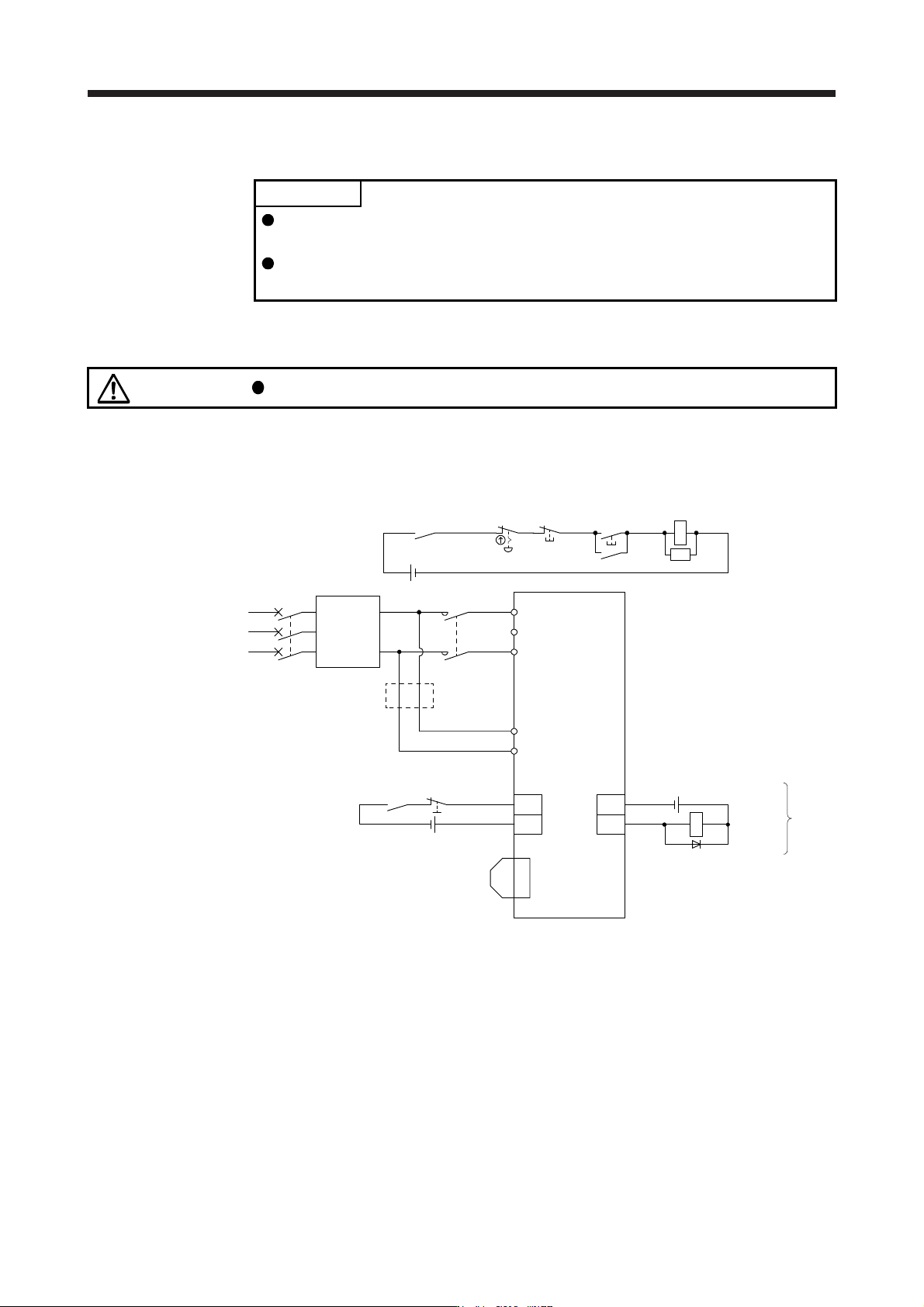
(1) MR-J4-10B-RJ to MR-J4-100B-RJ
(Note 2) Forced stop 2
MC (Note 3)
ALM
DOCOM
CN3
(Note 2)
24 V DC (Note 6)
24 V DC (Note 6)
24 V DC (Note 7, 8)
Malfunction
(Note 9)
RA1
L1
L2
L3
3-phase or 1-phase
200 V AC to 240 V AC
Servo amplifier
L11
L21
Malfunction
RA1
OFF
MC
ON
MC
Emergency stop switch
CN3
EM2
CN8
(Note 5)
Short-circuit connector
(packed with the servo
amplifier)
(Note 4)
Main circuit power supply
MCCB
AC/DC
Converter
(283 V DC to
340 V DC)
SK
DOCOM
(Note 10)
+
-
(Note 1)
Note 1. For the power suppl
y
specifications, refer to section 1.3.
2. This diagram shows sink I/O interface. For source I/O interface, refer to section 3.8.3.
3. Use the magnetic contactor with an operation delay time (interval between current being applied to the coil until closure of
contacts) of 80 ms or less (160 ms or less for 5 kW or more). Depending on the main circuit voltage and operation pattern, bus
voltage decreases, and that may cause the forced stop deceleration to shift to the dynamic brake deceleration. When dynamic
brake deceleration is not required, dela
y
the time to turn off the ma
g
netic contactor.
4. Configure a circuit to turn off EM2 when the main circuit power is turned off to prevent an unexpected restart of the servo
amplifier.
5. When not usin
g
the STO function, attach the short-circuit connector came with a servo amplifier.
6. The illustration of the 24 V DC power supply is divided between input signal and output signal for convenience. However, they
can be configured by one.
7. Drivin
g
the on switch and off switch with the DC power suppl
y
meets IEC/EN 60204-1 requirements.
8. Do not use the 24 V DC interface power supply for the magnetic contactor DC power supply. Always use the power supply
designed exclusively for the magnetic contactor.
9. If ALM (Malfunction) output is disabled with the parameter, configure the power supply circuit which switches off the magnetic
contactor after detection of alarm occurrence on the servo s
y
stem controlle
r
side.
10. When wires used for L11 and L21 are thinner than wires used for L1 and L3, use a fuse. (Refer to app. 15.4.)
APPENDIX
App. - 52
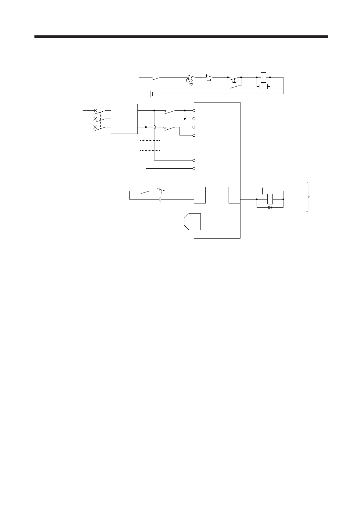
(2) MR-J4-200B-RJ to MR-J4-22KB-RJ
(Note 2) Forced stop 2
MC (Note 3)
(Note 2)
24 V DC (Note 6)
24 V DC (Note 6)
24 V DC (Note 7, 8)
Malfunction
(Note 9)
3-phase or 1-phase
200 V AC to 240 V AC
Servo amplifier
Malfunction
RA1
OFF
ON
Emergency stop switch
(Note 5)
Short-circuit connector
(packed with the servo
amplifier)
(Note 4)
Main circuit power supply
MCCB
AC/DC
Converter
(283 V DC to
340 V DC)
(Note 10)
(Note 1)
ALM
DOCOM
CN3
RA1
L1
L2
L3
L11
L21
N-
MC
MC
CN3
EM2
CN8
SK
DOCOM
+
-
Note 1. For the power suppl
y
specifications, refer to section 1.3.
2. This dia
g
ram shows sink I/O interface. For source I/O interface, refer to section 3.8.3.
3. Use a magnetic contactor with an operation delay time (interval between current being applied to the coil until closure of
contacts) of 80 ms or less (160 ms or less for 5 kW or more). Depending on the main circuit voltage and operation pattern, bus
voltage decreases, and that may cause the forced stop deceleration to shift to the dynamic brake deceleration. When dynamic
brake deceleration is not required, dela
y
the time to turn off the ma
g
netic contactor.
4. Configure a circuit to turn off EM2 when the main circuit power is turned off to prevent an unexpected restart of the servo
amplifier.
5. When not usin
g
the STO function, attach the short-circuit connector came with a servo amplifier.
6. The illustration of the 24 V DC power supply is divided between input signal and output signal for convenience. However, they
can be confi
g
ured b
y
one.
7. Drivin
g
the on switch and off switch with the DC power suppl
y
meets IEC/EN 60204-1 requirements.
8. Do not use the 24 V DC interface power supply for the magnetic contactor DC power supply. Always use the power supply
desi
g
ned exclusivel
y
for the ma
g
netic contactor.
9. If ALM (Malfunction) output is disabled with the parameter, configure the power supply circuit which switches off the magnetic
contactor after detection of alarm occurrence on the servo s
y
stem controlle
r
side.
10. When wires used for L11 and L21 are thinner than wires used for L1
/
L2
/
L3 and N-, use a fuse.
(
Refer to app. 15.4.
)
App. 15.2 Power supply capacity
The power supply capacity is the same as that for the AC power supply input. Refer to section 10.2 for
details.
APPENDIX
App. - 53
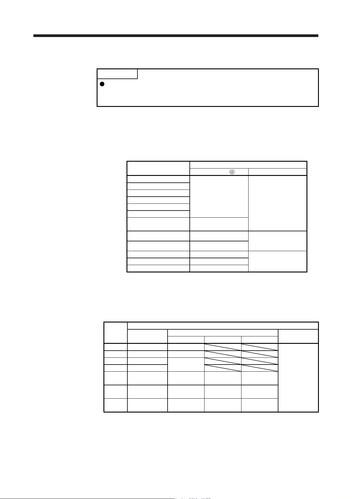
App. 15.3 Selection example of wires
POINT
Selection conditions of wire size are as follows.
Construction condition: Single wire set in midair
Wiring length: 30 m or shorter
The following diagram shows the wires used for wiring. Use the wires given in this section or equivalent.
(1) Example of selecting the wire sizes
Use the 600 V grade heat-resistant polyvinyl chloride insulated wire (HIV wire) for wiring. The following
shows the wire size selection example.
Servo amplifier
Wire [mm
2
] (Note 1)
L1/L2/L3/N-/ L11/L21
MR-J4-10B-RJ
2 (AWG 14)
1.25 to 2
(AWG 16 to 14)
MR-J4-20B-RJ
MR-J4-40B-RJ
MR-J4-60B-RJ
MR-J4-70B-RJ
MR-J4-100B-RJ
MR-J4-200B-RJ
MR-J4-350B-RJ
3.5 (AWG 12)
MR-J4-500B-RJ (Note 2) 5.5 (AWG 10): a
1.25 (AWG 16): a
2 (AWG 14): d
MR-J4-700B-RJ (Note 2) 8 (AWG 8): b
MR-J4-11KB-RJ (Note 2) 14 (AWG 6): e
1.25 (AWG 16): c
2 (AWG 14): c
MR-J4-15KB-RJ (Note 2) 22 (AWG 4): f
MR-J4-22KB-RJ (Note 2) 38 (AWG 2): g
Note 1.
A
lphabets in the table indicate crimping tools. For crimp terminals and applicable
tools, refer to
(
2
)
in this section.
2. To connect these models to a terminal block, be sure to use the screws that
come with the terminal block.
(2) Selection example of crimp terminals
Symbol
Servo amplifier-side crimp terminal
(Note 2)
Crimp terminal
Applicable tool
Manufacturer
Body Head Dice
a FVD5.5-4 YNT-1210S
JST
b (Note 1) 8-4NS YHT-8S
c FVD2-4
YNT-1614
d FVD2-M3
e FVD14-6 YF-1 YNE-38
DH-122
DH-112
f FVD22-6 YF-1 YNE-38
DH-123
DH-113
g FVD38-8 YF-1 YNE-38
DH-124
DH-114
Note 1. Coat the crimpin
g
part with an insulation tube.
2. Some crimp terminals may not be mounted depending on their sizes. Make sure to use the
recommended ones or equivalent ones.