sh030106u.pdf - 第650页
APPENDIX App. - 19 App. 5.1 1 Troubles hoot ing When power is not s upplie d or FAU LT LED t urns on, refer th e fol l owing tabl e and take the ap propriate action. Event Definition Cause Act ion Power is not supplied. …
APPENDIX
App. - 18
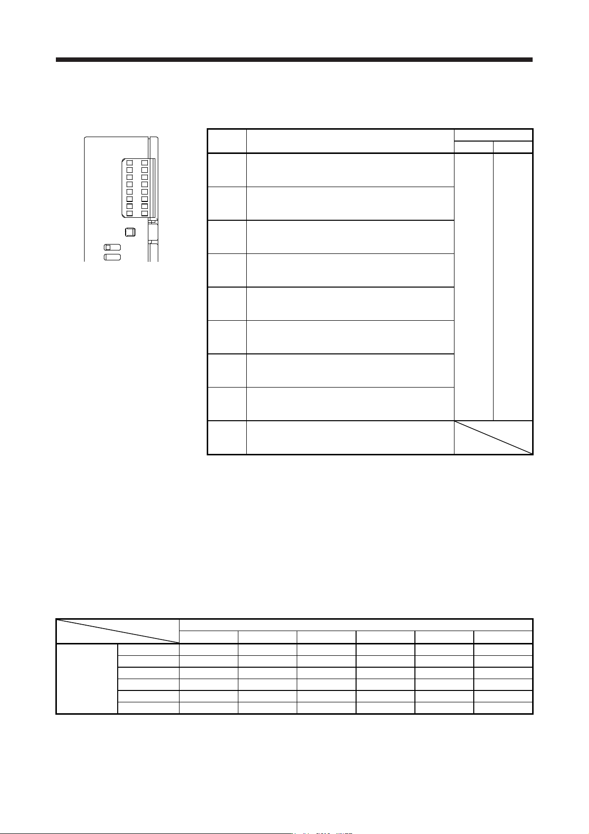
App. 5.9 LED display
I/O status, malfunction and power on/off are displayed with LED for each A-axis and B-axis.
MR-J3-D05
SRES
AB
SDI1
SDI2
TOF
SDO1
SDO2
SW
FAULT
POWER
LED Definition
LED
Column A Column B
SRES
Monitor LED for start/reset
Off: The start/reset is off. (The switch contact is opened.)
On: The start/reset is on. (The switch contact is closed.)
A-axis B-axis
SDI1
Monitor LED for shut-off 1
Off: The shut-off 1 is off. (The switch contact is closed.)
On: The shut-off 1 is on. (The switch contact is opened.)
SDI2
Monitor LED for shut-off 2
Off: The shut-off 2 is off. (The switch contact is closed.)
On: The shut-off 2 is on. (The switch contact is opened.)
TOF
Monitor LED for STO state
Off: Not in STO state
On: In STO state
SDO1
Monitor LED for SDO1
Off: Not in STO state
On: In STO state
SDO2
Monitor LED for SDO2
Off: Not in STO state
On: In STO state
SW
Monitor LED for confirming shutdown delay setting
Off: The settings of SW1 and SW2 do not match.
On: The settings of SW1 and SW2 match.
FAULT
FAULT LED
Off: Normal operation (STO monitoring state)
On: Fault has occurred.
POWER
Power
Off: Power is not supplied to MR-J3-D05.
On: Power is being supplied to MR-J3-D05.
App. 5.10 Rotary switch setting
Rotary switch is used to shut off the power after control stop by SS1 function.
Set the delay time from when the STO shut off switch is pressed until when STO output is performed. Set the
same setting for SW1 and SW2. The following table shows the delay time to be set according to the setting
value of the rotary switch.
Setting cannot be changed while power is on. Notify users that setting cannot be changed by putting a seal
or by another method so that end users will not change the setting after the shipment.
0 to F in the following table is the set value of the rotary switches (SW1 and SW2).
Rotary switch setting and delay time at A-axis/B-axis [s]
B-axis
0 s 1.4 s 2.8 s 5.6 s 9.8 s 30.8 s
0 s 0 1 2 - 3 4
1.4 s - - 5 - 6 7
A-axis
2.8 s - - 8 - 9 A
5.6 s - - - - B C
9.8 s - - - - D E
30.8 s - - - - - F
APPENDIX
App. - 19
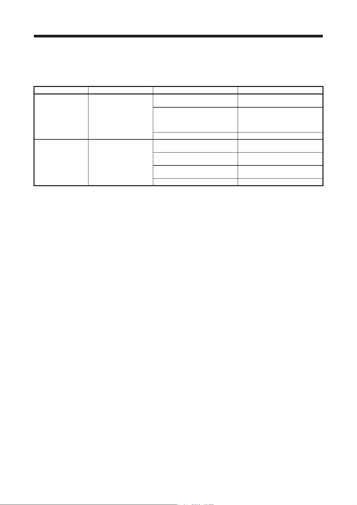
App. 5.11 Troubleshooting
When power is not supplied or FAULT LED turns on, refer the following table and take the appropriate
action.
Event Definition Cause Action
Power is not supplied.
Power LED does not turn on
although power is supplied.
1. 24 V DC power supply is
malfunctioning.
Replace the 24 V DC power supply.
2. Wires between MR-J3-D05 and 24
V DC power supply are
disconnected or are in contact with
other wires.
Check the wiring.
3. MR-J3-D05 is malfunctioning. Replace the MR-J3-D05.
FAULT LED is on.
FAULT LED of A-axis or B-
axis is on, and will not turn
off.
1. The delay time settings are not
matched.
Check the settings of the rotary
switch.
2. Switch input error
Check the wiring or sequence of the
input signals.
3. TOF signal error
Check the connection with the servo
amplifier.
4. MR-J3-D05 is malfunctioning. Replace the MR-J3-D05.
APPENDIX
App. - 20
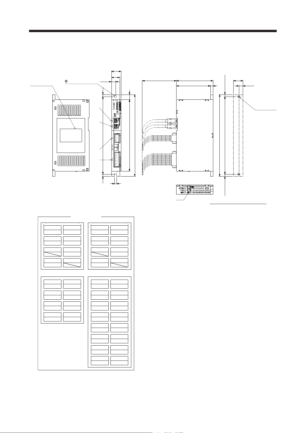
App. 5.12 Dimensions
[Unit: mm]
Rating plate
51825
192
5
FG
9.75
5 mounting hole
12168
6
86
80
2-M4 screw
Approx. 22.5
9.75
Approx. 192
Approx. 5Approx. 5
182
Approx. 80
Mounting hole process drawing
19.5
22.5
CN8ACN8BCN9CN10
78 78
TOF2A TOF1A TOF2B TOF1B
56 56
STO2A- STO2A+ STO2B- STO2B+
34 34
STO1A+ STO1B+
12 12
STO1A- STO1B-
1A 1B 1A 1B
SDI1A+ SDI1A- SRESA+ SRESA-
2A 2B 2A 2B
SDI1B+ SDI1B- SRESB+ SRESB-
3A 3B 3A 3B
SDO1B+ SDO1B- SDI2A+ SDI2A-
4A 4B 4A 4B
SDO1A+ SDO1A- SDI2B+ SDI2B-
5A 5B
SDO2B+ SDO2B-
6A 6B
SDO2A+ SDO2A-
7A 7B
+24 V 0 V
8A 8B
TOFA TOFB
CN8A CN8B
Pin assignment
CN9 CN10
Mounting screw
Screw size: M4
Tightening torque: 1.2 N•m
Mass: 0.2 [kg]