sh030106u.pdf - 第295页
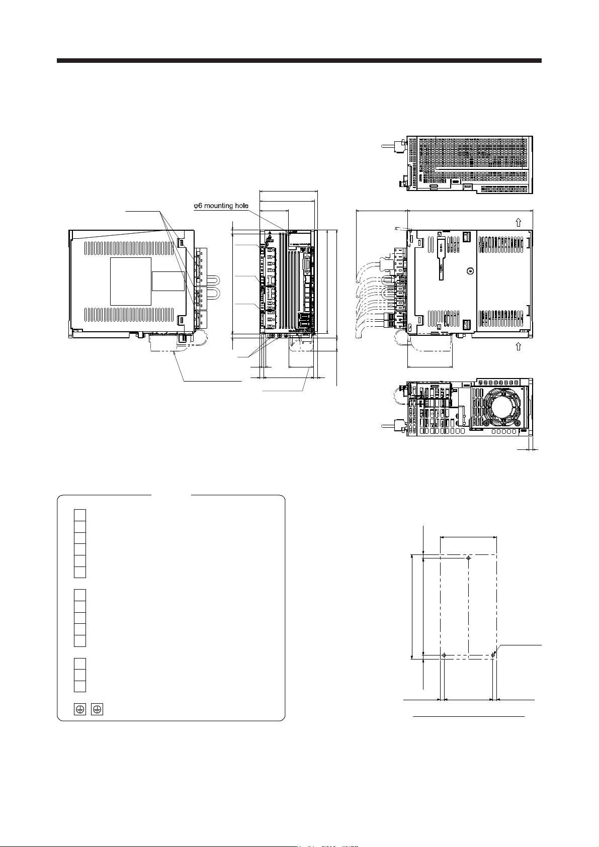
9. DIMENSIONS 9 - 12 (b) MR-J4-200B4(-RJ) [Unit: mm] 6 6 6 78 6 168 6 156 45 90 85 195 161 6 PE CNP1 CNP2 CNP3 Cooli ng fan air intake Approx. 69.3 With MR-BAT6V1 SET Lock knob Exhaust Approx. 80 Approx. 21 Approx. 38.5 …
9. DIMENSIONS
9 - 11
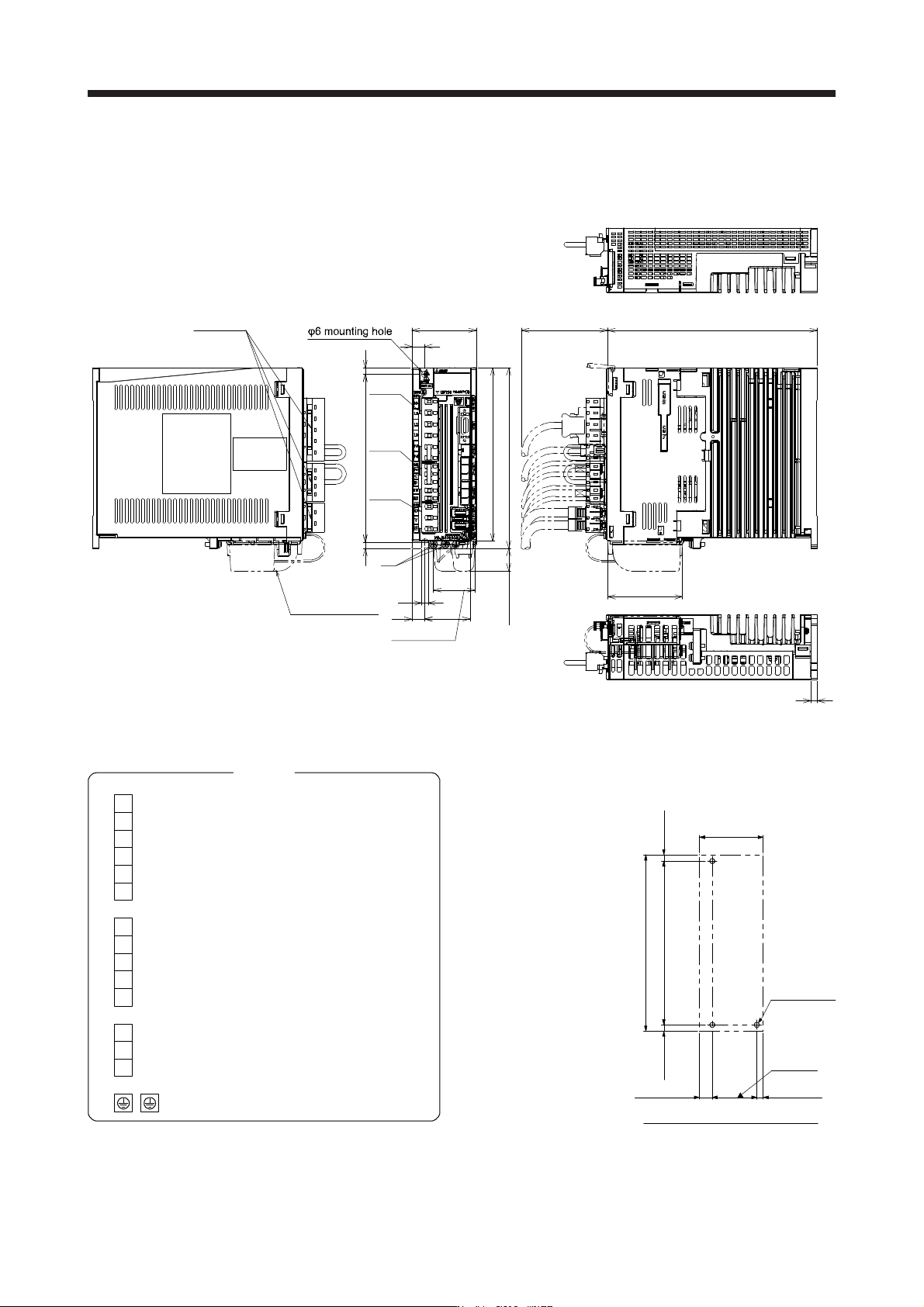
(2) 400 V class
(a) MR-J4-60B4(-RJ)/MR-J4-100B4(-RJ)
[Unit: mm]
12
156
6
42
6
60
6
12
CNP1
195
6
168
161
PE
CNP2
CNP3
Lock knob
Approx. 80
Approx. 21
Approx. 69.3
With
MR-BAT6V1 SET
Approx. 38.5
Mass: 1.7 [kg]
L2
N-
P3
L11
L21
P4
L3
L1
C
D
P+
PE
Terminal
CNP1
CNP2
V
W
U
CNP3
Screw size: M4
Tightening torque: 1.2 [N•m]
Mounting screw
Screw size: M5
Tightening torque: 3.24 [N•m]
42 ± 0.3
156 ± 0.5
Approx. 60
Approx.
6
Approx. 168
3-M5 screw
Approx. 6
Approx.
6
Approx. 12
Mounting hole process drawing
9. DIMENSIONS
9 - 12
(b) MR-J4-200B4(-RJ)
[Unit: mm]
6
6
6
78 6
168
6156
45
90
85
195
161
6
PE
CNP1
CNP2
CNP3
Cooling fan
air intake
Approx. 69.3
With
MR-BAT6V1 SET
Lock knob
Exhaust
Approx. 80
Approx. 21
Approx. 38.5
Mass: 2.1 [kg]
L2
N-
P3
L11
L21
P4
L3
L1
C
D
P+
PE
Terminal
CNP1
CNP2
V
W
U
CNP3
Screw size: M4
Tightening torque: 1.2 [N•m]
Mounting screw
Screw size: M5
Tightening torque: 3.24 [N•m]
156 ± 0.5
78 ± 0.3
Approx. 168
3-M5 screw
Approx. 90
Approx. 6Approx. 6
Approx.
6
Approx.
6
Mounting hole process drawing
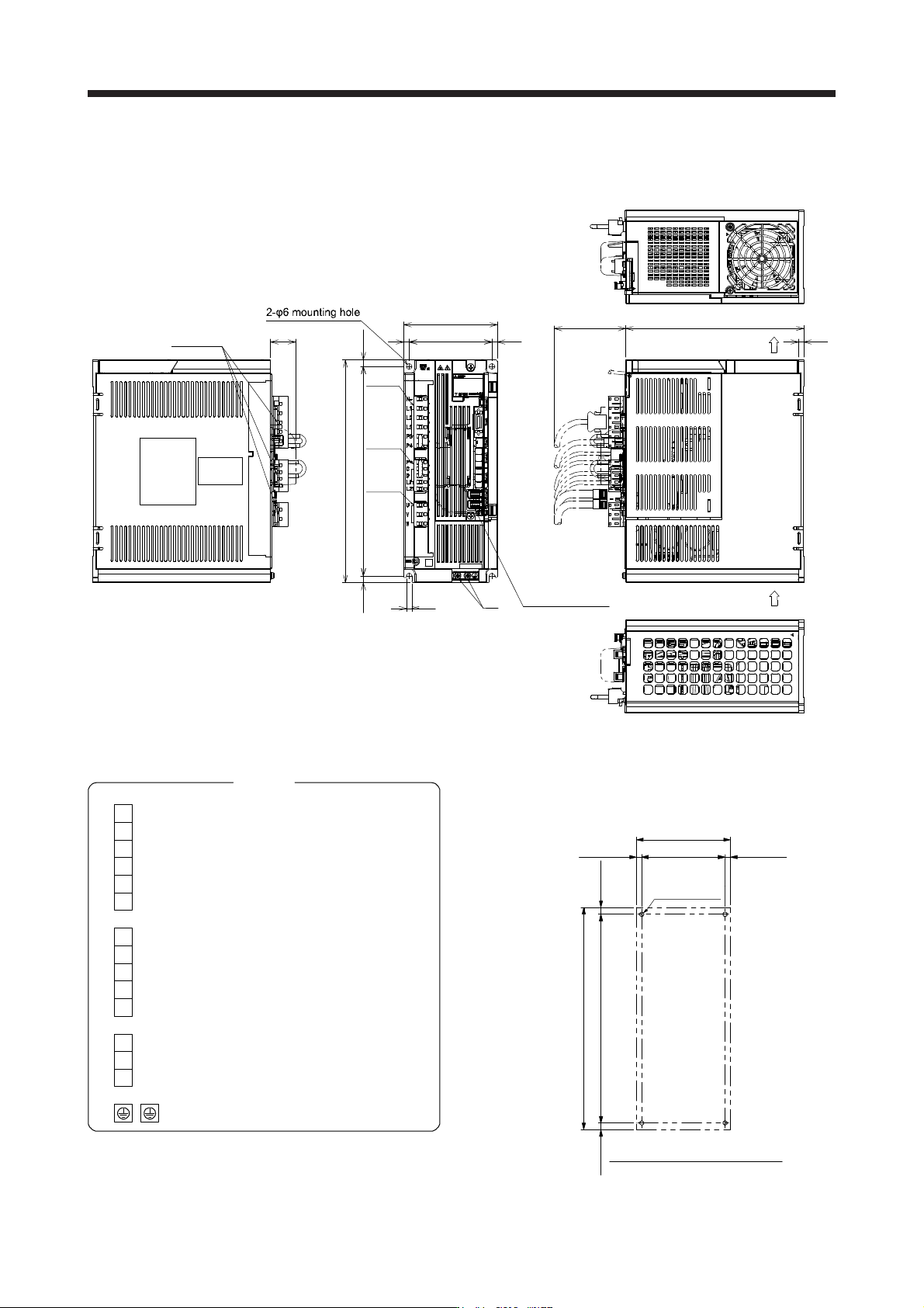
9. DIMENSIONS
9 - 13
(c) MR-J4-350B4(-RJ)
[Unit: mm]
105
93 66
7.5 235
200
6
250
7.5
6
CNP1
CNP2
CNP3
PE
Approx. 80
Cooling fan exhaust
Intake
With
MR-BAT6V1 SET
Lock knob
Approx. 28
Mass: 3.6 [kg]
L2
N-
P3
L11
L21
P4
L3
L1
C
D
P+
PE
Terminal
CNP1
CNP2
V
W
U
CNP3
Screw size: M4
Tightening torque: 1.2 [N•m]
Mounting screw
Screw size: M5
Tightening torque: 3.24 [N•m]
235 ± 0.5
93 ± 0.5
Approx. 6Approx. 6
4-M5 screw
A
pprox. 105
Approx. 250
Mounting hole process drawing
Approx.
7.5
Approx.
7.5