sh030106u.pdf - 第482页
14. USIN G A LINEAR SER VO MOTOR 14 - 15 (3) Operation at the m agnetic pole de tection WARNING Note that the mag netic po le detec tion aut omatic ally s tarts simu lt aneous ly with the turning-on of the s ervo-on c om…
14. USING A LINEAR SERVO MOTOR
14 - 14
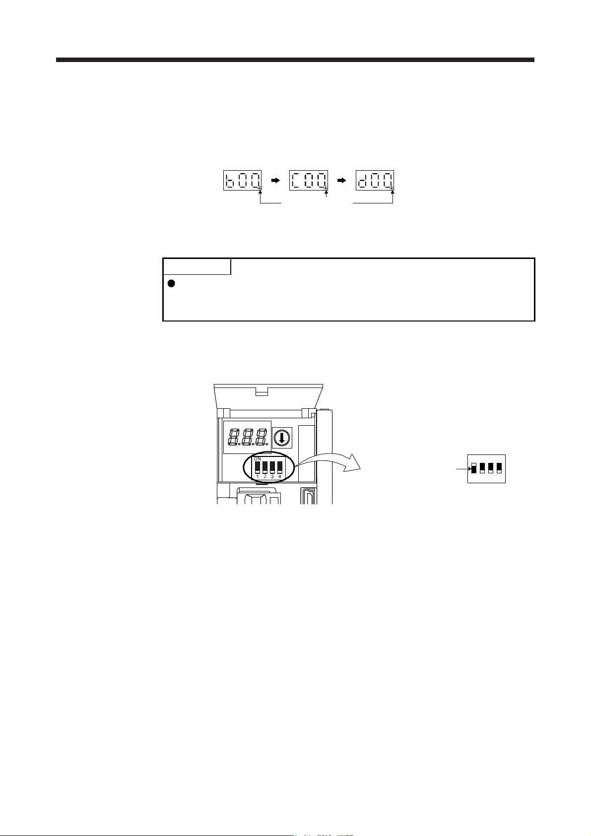
(c) State transition of the servo amplifier display (3-digit, 7-segment LED) at the magnetic pole detection
When the magnetic pole detection with MR Configurator2 is normally executed, the servo amplifier
display (3-digit, 7-segment LED) shows the state as below.
The decimal point
blinks.
Servo-off status
During the
magnetic pole
detection
Magnetic pole
detection
completion
(servo-on status)
(2) Preparation for the magnetic pole detection
POINT
When the test operation mode is selected with the test operation select switch
(SW2-1), the SSCNET III/H communication for the servo amplifier in the test
operation mode and the following servo amplifiers is blocked.
For the magnetic pole detection, use the test operation mode (positioning operation) of MR
Configurator2. Turn off the servo amplifier power, and set the test operation select switch (SW2-1) as
shown below. Turning on the power enables the test operation mode.
Set SW2-1 to "ON (up)".
1
ON
2 3 4
14. USING A LINEAR SERVO MOTOR
14 - 15
(3) Operation at the magnetic pole detection
WARNING
Note that the magnetic pole detection automatically starts simultaneously with the
turning-on of the servo-on command.
CAUTION
If the magnetic pole detection is not executed properly, the linear servo motor may
operate unexpectedly.
POINT
Establish the machine configuration using FLS (Upper stroke limit) and RLS
(Lower stroke limit). Otherwise, the machine may be damaged due to a collision.
At the magnetic pole detection, whether the linear servo motor moves in the
positive or negative direction is unpredictable.
Depending on the setting value of [Pr. PL09 Magnetic pole detection voltage
level], an overload, overcurrent, magnetic pole detection alarm, or others may
occur.
When performing the positioning operation from a controller, use the sequence
which confirms the normal completion of the magnetic pole detection and the
servo-on status, then outputs the positioning command. If the controller outputs
the positioning command before RD (Ready) turns on, the command may not be
accepted or a servo alarm may occur.
After the magnetic pole detection, check the positioning accuracy with the test
operation (positioning operation function) of MR Configurator2.
When the absolute position linear encoder is used, if a gap is generated to the
positional relation between the linear encoder and the linear servo motor,
perform the magnetic pole detection again.
The accuracy of the magnetic pole detection improves with no load.
An alarm may occur when the linear encoder is not mounted properly, or when
the linear encoder resolution setting ([Pr. PL02] and [Pr. PL03]) or the setting
value of [Pr. PL09 Magnetic pole detection voltage level] is incorrect.
For the machine that its friction becomes 30% or more of the continuous thrust,
the linear servo motor may not operate properly after the magnetic pole
detection.
For the horizontal shaft of the machine that its unbalanced thrust becomes 20%
or more of the continuous thrust, the linear servo motor may not operate
properly after the magnetic pole detection.
For the machine that multiple axes are connected like a tandem configuration, if
you try to perform the magnetic pole detection simultaneously for multiple axes,
the magnetic pole detection may not be executed. Perform the magnetic pole
detection for each axis. At this time, set the axes that the magnetic pole
detection is not performed for to servo-off.
14. USING A LINEAR SERVO MOTOR
14 - 16
(a) For the incremental linear encoder
POINT
For the incremental linear encoder, the magnetic pole detection is required every
time the power is turned on.
By turning on the servo-on command from the controller after the power-on, the magnetic pole
detection is automatically carried out. Therefore, there is no need to set the parameter (first digit of
[Pr. PL01]) for executing the magnetic pole detection.
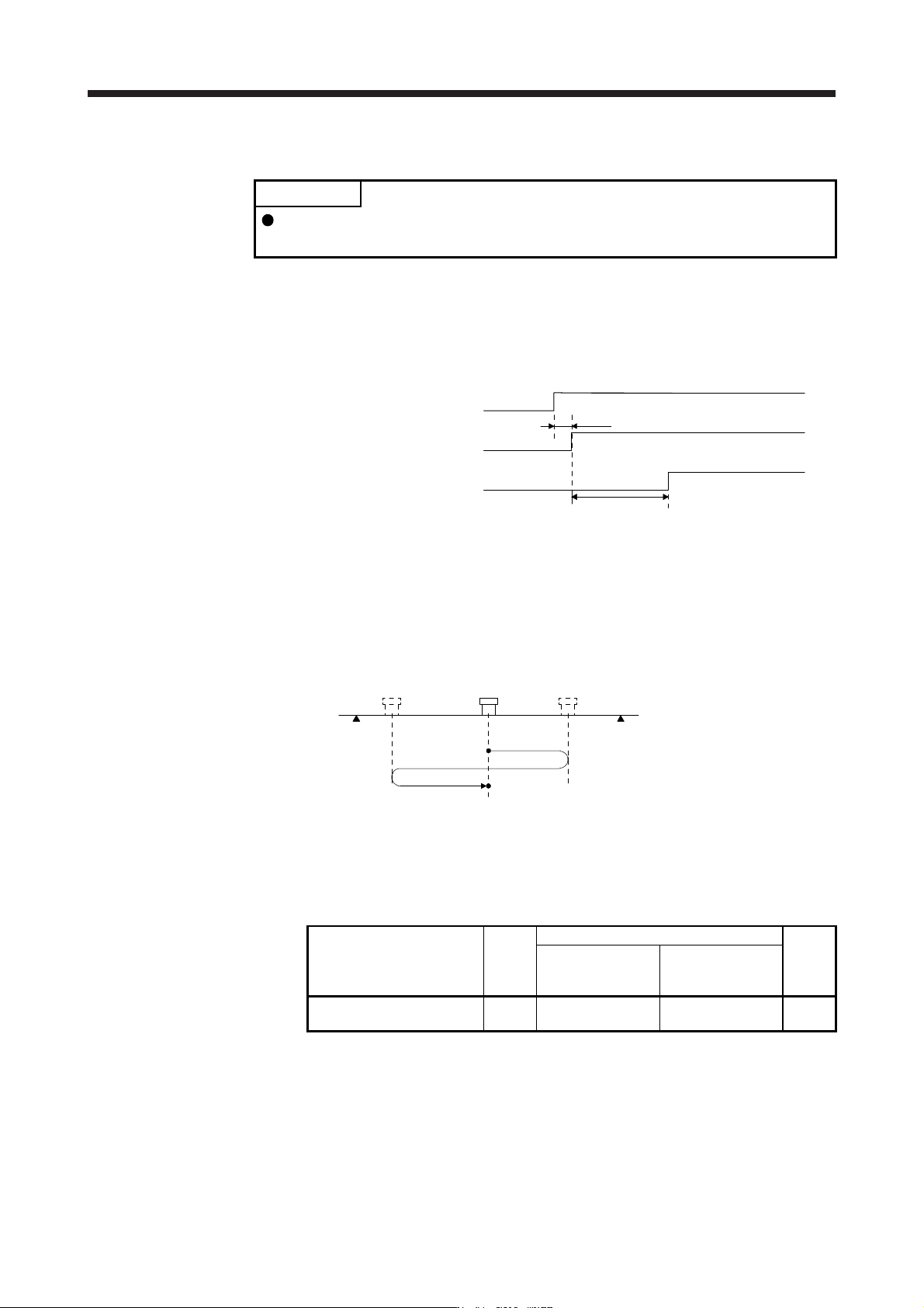
1) Timing chart
15 s or less
ON
OFF
ON
OFF
ON
OFF
95 ms
Servo-on command
Base circuit
RD (Ready)
Magnetic pole detection time (Note)
Note. The magnetic pole detection time indicates the operation time when FLS (Upper
stroke limit
)
and RLS
(
Lower stroke limit
)
are on.
2) Linear servo motor movement (when FLS (Upper stroke limit) and RLS (Lower stroke limit) are
on)
RLS
(Note 1)
FLS
(Note 1)
(Note 2)
Magnetic pole detection completion position
Servo-on position
(Magnetic pole detection start position)
Note 1. When you turn off FLS (Upper stroke limit) or RLS (Lower stroke limit) during the magnetic pole detection, the operation of the
magnetic pole detection is carried on to the opposite direction. When both FLS and RLS are off, [AL. 27 Initial magnetic pole
detection error] occurs.
2. The followin
g
shows the pitch a
g
ainst the ma
g
netic pole.
Linear servo motor series
LM-H3
LM-F
LM-U2
LM-K2
Medium thrust
(Continuous thrust:
Less than 400 N)
Large thrust
(Continuous thrust:
400 N or more)
Pitch against magnetic pole
[mm]
48 30 60 48