sh030106u.pdf - 第565页
17. APPLICATIO N OF FUNCTIONS 17 - 14 2) Select " MR-J3-B extensi on func tion" of model se lect ion in t h e "New" w indow and cl ick " OK". The "Extensio n func tion chan ge" win…
17. APPLICATION OF FUNCTIONS
17 - 13
The following shows how to use the J3 extension function.
(1) Settings of J3 extension function
POINT
To set the J3 extension function, connect a personal computer with MR
Configurator2 of software version 1.25B or later to the servo amplifier with USB
cable.
The extension control 2 parameters ([Pr. PX_ _ ]) cannot be set from a
controller.
To use the J3 the extension function, enable the setting of the extension control 2 parameters ([Pr. PX_
_ ]). Set as follows using MR Configurator2.
(a) Setting to enable the extension control 2 parameters ([Pr. PX_ _ ])
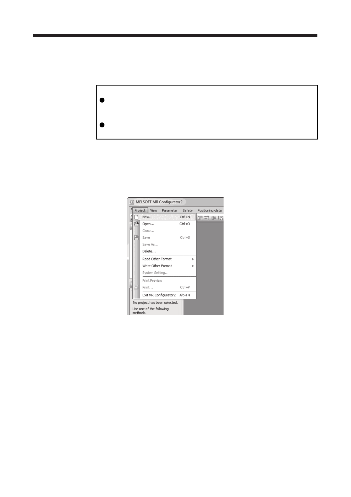
1) Open the "Project" menu and click "New" in MR Configurator2. The "New" window will be
displayed.
17. APPLICATION OF FUNCTIONS
17 - 14
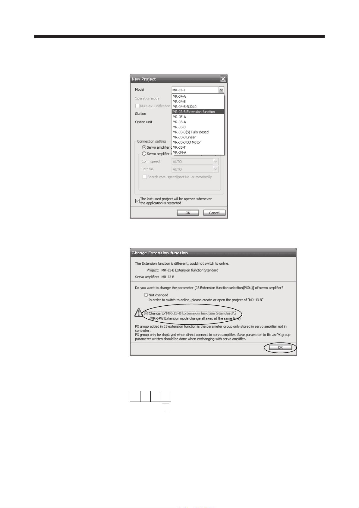
2) Select "MR-J3-B extension function" of model selection in the "New" window and click "OK". The
"Extension function change" window will be displayed.
3) Click "Change to MR-J3-B extension function" in the "Extension function change" window and
click "OK". Now, you can set the extension control 2 parameters ([Pr. PX_ _ ]).
(b) Setting to enable the J3 extension function
To enable the J3 extension function, set [Pr. PX01] to "_ _ _ 1".
000
[Pr. PX01]
J3 extension function selection
0: Disabled
1: Enabled
17. APPLICATION OF FUNCTIONS
17 - 15
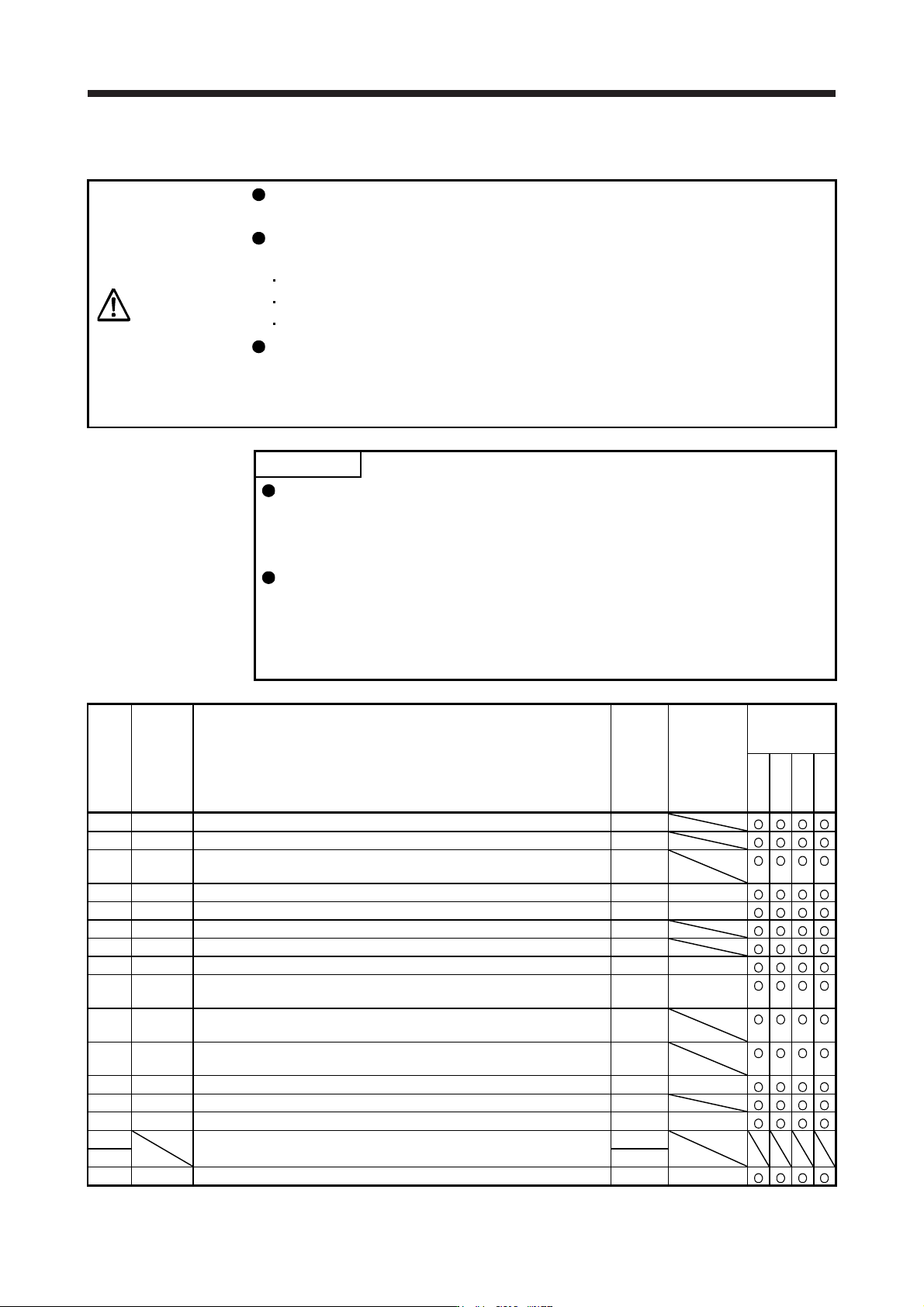
(2) Extension control 2 parameters ([Pr. PX_ _ ])
CAUTION
Never make a drastic adjustment or change to the parameter values as doing so
will make the operation unstable.
Do not change the parameter settings as described below. Doing so may cause
an unexpected condition, such as failing to start up the servo amplifier.
Changing the values of the parameters for manufacturer setting
Setting a value out of the range
Changing the fixed values in the digits of a parameter
When you write parameters with the controller, make sure that the control axis No.
of the servo amplifier is set correctly. Otherwise, the parameter settings of another
axis may be written, possibly causing the servo amplifier to be an unexpected
condition.
POINT
The parameter whose symbol is preceded by * is enabled with the following
conditions:
*: After setting the parameter, cycle the power or reset the controller.
**: After setting the parameter, cycle the power.
Abbreviations of J3 compatibility mode indicate the followings.
Standard: Standard (semi closed loop system) use of the rotary servo motor
Full.: Fully closed loop system use of the rotary servo motor
Lin.: Linear servo motor use
DD: Direct drive (DD) motor use
No. Symbol Name
Initial
value
Unit
J3
compatibility
mode
Standard
Full.
Lin.
DD
PX01 **J3EX J3 extension function 0000h
PX02 XOP1 Function selection X-1 0000h
PX03 VRFTX
Vibration suppression control tuning mode (advanced vibration
suppression control II)
0000h
PX04 VRF21 Vibration suppression control 2 - Vibration frequency 100.0 [Hz]
PX05 VRF22 Vibration suppression control 2 - Resonance frequency 100.0 [Hz]
PX06 VRF23 Vibration suppression control 2 - Vibration frequency damping 0.00
PX07 VRF24 Vibration suppression control 2 - Resonance frequency damping 0.00
PX08 VRF21B Vibration suppression control 2 - Vibration frequency after gain switching 0.0 [Hz]
PX09 VRF22B
Vibration suppression control 2 - Resonance frequency after gain
switching
0.0 [Hz]
PX10 VRF23B
Vibration suppression control 2 - Vibration frequency damping after gain
switching
0.00
PX11 VRF24B
Vibration suppression control 2 - Resonance frequency damping after
gain switching
0.00
PX12 PG1B Model loop gain after gain switching 0.0 [rad/s]
PX13 *XOP2 Function selection X-2 0001h
PX14 OTHOV One-touch tuning - Overshoot permissible level 0 [%]
PX15
For manufacturer setting 0000h
PX16 0000h
PX17 NH3 Machine resonance suppression filter 3 4500 [Hz]