sh030106u.pdf - 第629页
17. APPLICATIO N OF FUNCTIONS 17 - 78 (4) MR-J4FCCBL03 M branc h cable Use MR-J4FCC BL03M br anch cabl e to conn ect the scale meas ureme nt enc oder to CN2 co nnect or. When fabr icating the br anch c able usi ng MR-J 3…
17. APPLICATION OF FUNCTIONS
17 - 77
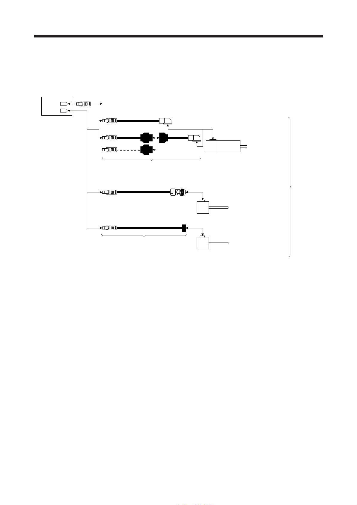
2) MR-J4-_B_-RJ servo amplifier
You can connect the rotary encoder without using a branch cable shown in 1) for MR-J4-_B-RJ
servo amplifier. In addition, a four-wire type or A/B/Z-phase differential output rotary encoder can
also be used.
CN2
CN2L
Q170ENCCBL_M-A
HG-KR
HG-MR
Servo amplifier
Encoder of rotary servo motor
Encoder cable
(Refer to "Servo Motor Instruction Manual (Vol. 3)".)
Scale
measurement
encoder
Servo motor
Synchronous encoder Q171ENC-W8
Encoder cable
(Refer to "Linear Encoder Instruction Manual".)
A/B/Z-phase differential output rotary
encoder (Note)
Note.
A
/B/Z-phase differential output rotary encoders with the same specifications as A/B/Z-phase differential output linear encoders can
be used as scale measurement encoders. Refer to "Linear Encoder Instruction Manual".
17. APPLICATION OF FUNCTIONS
17 - 78
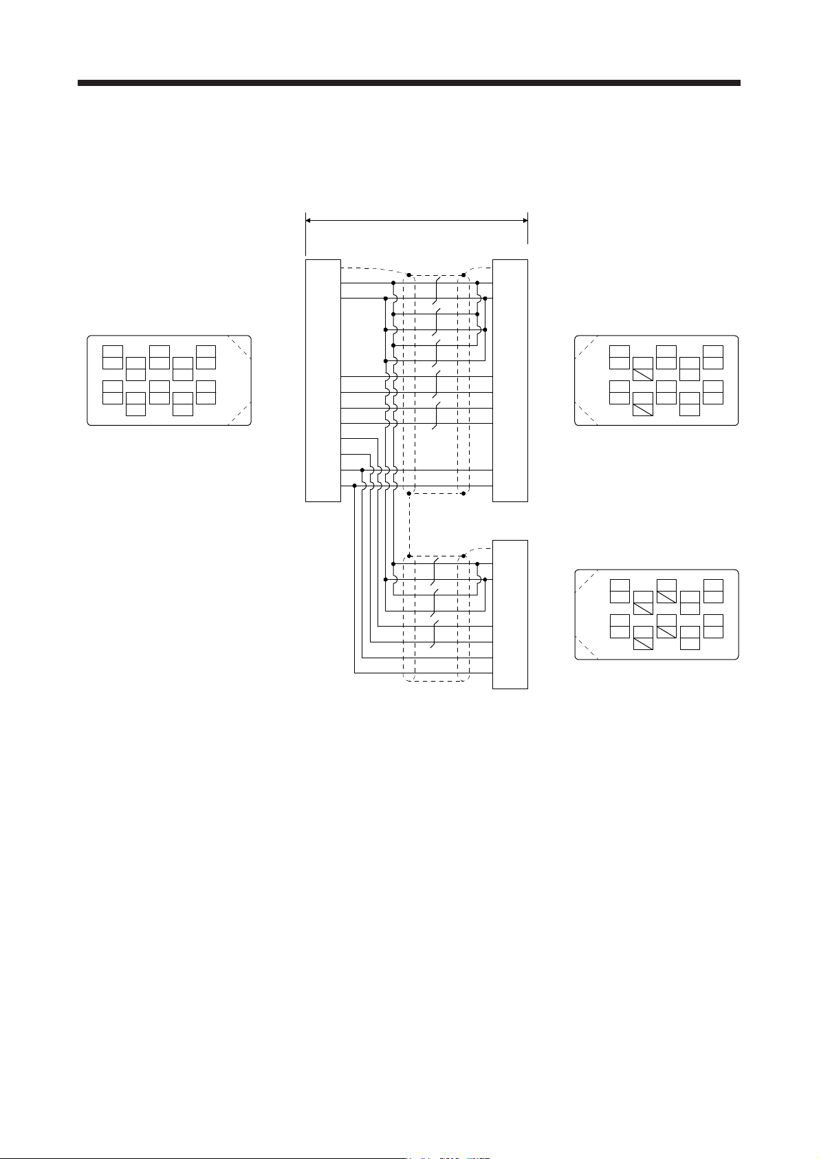
(4) MR-J4FCCBL03M branch cable
Use MR-J4FCCBL03M branch cable to connect the scale measurement encoder to CN2 connector.
When fabricating the branch cable using MR-J3THMCN2 connector set, refer to "Linear Encoder
Instruction Manual".
LG
View seen from the wiring side.
4
MRR
2
LG
8
6
1
P5
5
10
3
MR
7
9
THM2
THM1
MXR
SEL
THM2
THM1
SEL
MX
BAT
SD
3
4
1
CN2 MOTOR
Plate
(Note 1) (Note 2)
0.3 m
MR
P5
MRR
SD
MR
P5
MRR
3
4
1
Plate
View seen from the wiring side.
4
MRR
2
8
6
1
P5
5
10
3
MR
7
9
View seen from the wiring side.
4
2
8
6
15
10
37
9
BAT
2
THM2 6
7
MX
LG LG2
MXR 8
BAT
SEL
9
10
5THM1 5 THM1
6 THM2
9 BAT
10 SEL
SCALE
(Note 2)
P5
SD
SEL
LG
1
2
10
Plate
4 MXR
BAT9
3MX
BAT
SEL
LG
P5
MXR
MX
Note 1. Receptacle: 36210-0100PL, shell kit: 36310-3200-008
(
3M
)
2. Plu
g
: 36110-3000FD, shell kit: 36310-F200-008
(
3M
)
17. APPLICATION OF FUNCTIONS
17 - 79
17.3.3 How to use scale measurement function
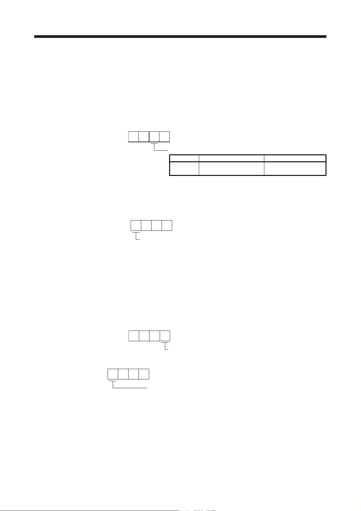
(1) Selection of scale measurement function
The scale measurement function is set with the combination of basic setting parameters [Pr. PA01] and
[Pr. PA22].
(a) Operation mode selection
The scale measurement function can be used during semi closed loop system (standard control
mode). Set [Pr. PA01] to "_ _ 0 _".
Operation mode selection
[Pr. PA01]
10 0
Semi closed loop system
(Standard control mode)
Setting value
0
Operation mode
Servo motor-side
resolution unit
Control unit
(b) Scale measurement function selection
Select the scale measurement function. Select "1 _ _ _" (Used in absolute position detection system)
or "2 _ _ _" (Used in incremental system) according to the encoder you use.
Scale measurement function selection
0: Disabled
1: Used in absolute position detection system
2: Used in incremental system
000
[Pr. PA22]
(2) Selection of scale measurement encoder communication method and polarity.
The communication method differs depending on the scale measurement encoder type. For the
communication method for using a linear encoder as scale measurement encoder, refer to "Linear
Encoder Instruction Manual". Select "Four-wire type" because there is only four-wire type for
synchronous encoder.
Select the cable to be connected to CN2L connector in [Pr. PC26].
000
[Pr. PC27]
Encoder pulse count polarity selection
0: Load-side encoder pulse increasing direction in the servo motor CCW
1: Load-side encoder pulse decreasing direction in the servo motor CCW
00
[Pr. PC26]
Load-side encoder cable communication method selection
0: Two-wire type
1: Four-wire type
When using a load-side encoder of A/B/Z-phase differential output method, set "0"
.
Incorrect setting will trigger [AL. 70] and [AL. 71].
Setting "1" while using an MR-J4-_B_ servo amplifier will trigger [AL. 37].
If the settings of the servo amplifier are unchanged from the factory settings and
communication with the controller is performed for the first time, this digit will be
automatically set according to the communication method of the connected
encoder cable.
0