sh030106u.pdf - 第129页
4. STA RTUP 4 - 4 (c) When you us e an op tion a nd auxi liary equ ipment 1) 200 V c lass a) When you use a re generat ive opt ion for 5 kW or less servo am plifie rs The lead wire betw een P+ termin al and D ter minal s…
4. STARTUP
4 - 3
4.1.2 Wiring check
(1) Power supply system wiring
Before switching on the main circuit and control circuit power supplies, check the following items.
(a) Power supply system wiring
1) The power supplied to the power input terminals (L1/L2/L3/L11/L21) of the servo amplifier should
satisfy the defined specifications. (Refer to section 1.3.)
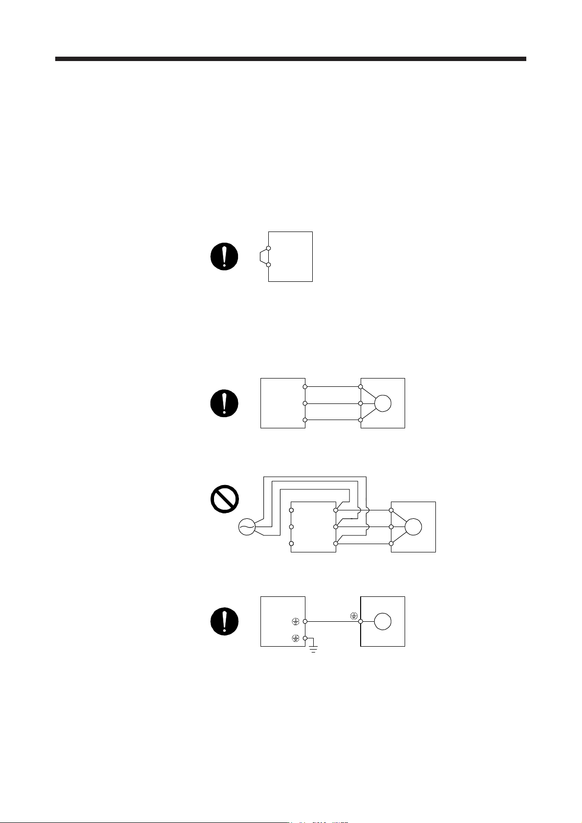
2) When the power factor improving DC reactor is not used, between P3 and P4 should be
connected.
P3
P4
Servo amplifier
(Note)
Note. The 100 V class servo amplifiers do not have P3 and P4.
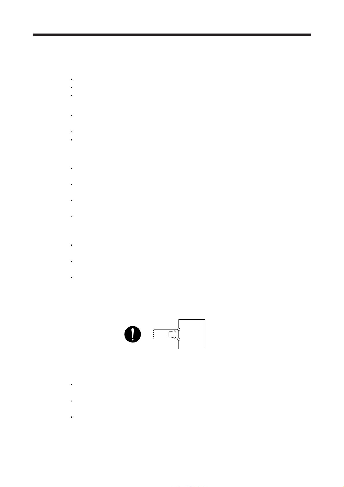
(b) Connection of servo amplifier and servo motor
1) The servo amplifier power output (U/V/W) should match in phase with the servo motor power
input terminals (U/V/W).
Servo amplifier Servo motor
M
U
V
W
U
V
W
2) The power supplied to the servo amplifier should not be connected to the servo motor power
terminals (U/V/W). Otherwise, the servo amplifier and servo motor will malfunction.
Servo amplifier Servo motor
M
U
V
W
U
V
W
L1
L2
L3
3) The grounding terminal of the servo motor is connected to the PE terminal of the servo amplifier.
Servo amplifie
r
Servo moto
r
M
4) The CN2 connector of the servo amplifier should be connected to the encoder of the servo motor
securely using the encoder cable.
4. STARTUP
4 - 4
(c) When you use an option and auxiliary equipment
1) 200 V class
a) When you use a regenerative option for 5 kW or less servo amplifiers
The lead wire between P+ terminal and D terminal should not be connected.
The regenerative option wire should be connected between P+ and C terminal.
Twisted wires cable should be used. (Refer to section 11.2.4.)
b) When you use a regenerative option for 7 kW or more servo amplifiers
For 7 kW servo amplifiers, the lead wire of the built-in regenerative resistor connected to P+
terminal and C terminal should not be connected.
The regenerative option wire should be connected between P+ and C terminal.
Twisted wires cable should be used. (Refer to section 11.2.4.)
c) When you use a brake unit and power regeneration converter for 5 kW or more servo
amplifiers
For 5 kW or less servo amplifiers, the lead wire between P+ terminal and D terminal should
not be connected.
For 7 kW servo amplifiers, the lead wire of the built-in regenerative resistor connected to P+
terminal and C terminal should not be connected.
Brake unit, power regeneration converter should be connected to P+ terminal and N-
terminal. (Refer to section 11.3 and 11.4.)
Twisted wires cable should be used when wiring is over 5 m and equal to or less than 10 m
using a brake unit. (Refer to section 11.3)
d) When you use a power regeneration common converter
For 5 kW or less servo amplifiers, the lead wire between P+ terminal and D terminal should
not be connected.
For 7 kW servo amplifiers, the lead wire of built-in regenerative resistor connected to P+
terminal and C terminal should not be connected.
The wire of power regeneration common converter should be connected to P4 terminal and
N- terminal. (Refer to section 11.5.)
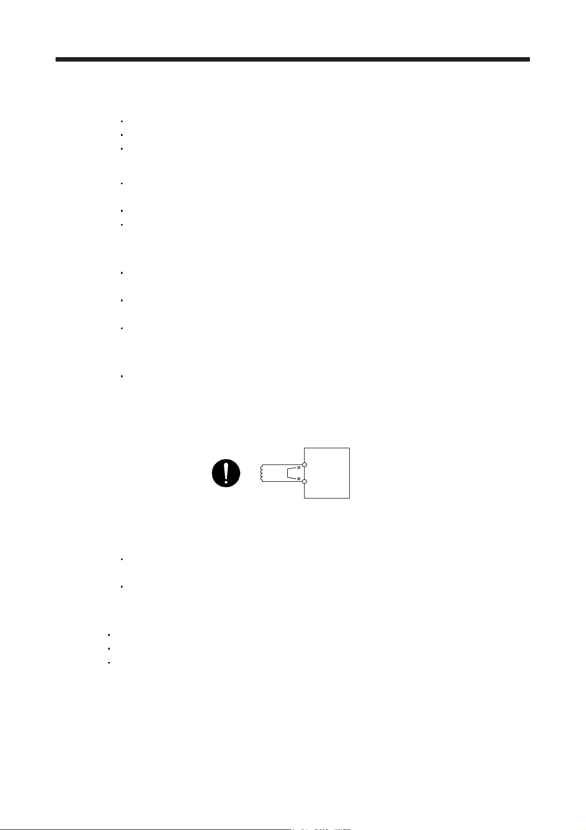
e) The power factor improving DC reactor should be connected between P3 and P4. (Refer to
section 11.11.)
(Note)
Power factor improving
DC reactor
Servo amplifier
P3
P4
Note.
A
lwa
y
s disconnect between P3 and P4 terminals.
f) When you use a multifunction regeneration converter
For 5 kW or less servo amplifiers, the lead wire between the P+ terminal and D terminal
should be connected. (factory-wired)
For 7 kW servo amplifiers, the lead wire of the built-in regenerative resistor connected to the
P+ terminal and C terminal should be connected. (factory-wired)
The wire of the multifunction regeneration converter should be connected to the P4 terminal
and N- terminal. (Refer to section 11.19.)
4. STARTUP
4 - 5
2) 400 V class
a) When you use a regenerative option for 3.5 kW or less servo amplifiers
The lead wire between P+ terminal and D terminal should not be connected.
The regenerative option should be connected to P+ terminal and C terminal.
Twisted wires cable should be used. (Refer to section 11.2.4.)
b) When you use a regenerative option for 5 kW or more servo amplifiers
For 5 kW or 7 kW servo amplifiers, the lead wire of the built-in regenerative resistor
connected to P+ terminal and C terminal should not be connected.
The regenerative option should be connected to P+ terminal and C terminal.
Twisted wires cable should be used. (Refer to section 11.2.4.)
c) When you use a brake unit and power regeneration converter for 5 kW or more servo
amplifiers
For 5 kW or 7 kW servo amplifiers, the lead wire of the built-in regenerative resistor
connected to P+ terminal and C terminal should not be connected.
Brake unit, power regeneration converter should be connected to P+ terminal and N-
terminal. (Refer to section 11.3 and 11.4.)
Twisted wires cable should be used when wiring is over 5 m and equal to or less than 10 m
using a brake unit. (Refer to section 11.3)
d) When you use a power regeneration common converter
Power regeneration common converter should be connected to P4 terminal and N- terminal.
(Refer to section 11.5.)
e) The power factor improving DC reactor should be connected between P3 and P4. (Refer to
section 11.11.)
(Note)
Power factor improving
DC reactor
Servo amplifier
P3
P4
Note.
A
lwa
y
s disconnect between P3 and P4.
f) When you use a multifunction regeneration converter
For 5 kW or 7 kW servo amplifiers, the lead wire of the built-in regenerative resistor
connected to the P+ terminal and C terminal should be connected. (factory-wired)
The wire of the multifunction regeneration converter should be connected to the P4 terminal
and N- terminal. (Refer to section 11.19.)
3) 100 V class
The lead wire between P+ terminal and D terminal should not be connected.
The regenerative option should be connected to P+ terminal and C terminal.
Twisted wires cable should be used. (Refer to section 11.2.4.)
(2) I/O signal wiring
(a) The I/O signals should be connected correctly.
Use DO forced output to forcibly turn on/off the pins of the CN3 connector. You can use this function
to check the wiring. In this case, switch on the control circuit power supply only.
Refer to section 3.2 for details of I/O signal connection.