sh030106u.pdf - 第618页
17. APPLICATIO N OF FUNCTIONS 17 - 67 5) Adjustin g the l ost moti on compens atio n timing When the m achin e has low rigi dity, the s peed loop gai n is set l ow er than th e standar d setting value, or the ser vo moto…

17. APPLICATION OF FUNCTIONS
17 - 66
4) Lost motion compensation timing ([Pr. PX41])
You can set the delay time of the lost motion compensation start timing with this parameter.
When a protrusion occurs belatedly, set the lost motion compensation timing corresponding to the
protrusion occurrence timing.
5) Lost motion compensation non-sensitive band ([Pr. PX42])
When the travel direction reverses frequently around the zero speed, unnecessary lost motion
compensation is triggered by the travel direction switching. By setting the lost motion
compensation non-sensitive band, the speed is recognized as 0 when the fluctuation of the droop
pulse is the setting value or less.
When the value of this parameter is changed, the compensation timing is changed. Adjust the
value of Lost motion compensation timing ([Pr. PX41]).
6) Lost motion filter setting ([Pr. PX38])
Changing the value of this parameter is usually unnecessary. When a value other than 0.0 ms is
set in this parameter, the high-pass filter output value of the set time constant is applied to the
compensation and lost motion compensation continues.
(b) Adjustment procedure of the lost motion compensation function
1) Measuring the load current
Measure the load currents during the forward direction feed and reverse direction feed with MR
Configurator2.
2) Setting the lost motion compensation
Calculate the friction torque from the measurement result of (9) (b) 1) in this section and set a
value twice the friction torque in [Pr. PX36] and [Pr. PX37] as lost motion compensation.
Friction torque [%] =
2
|(load current during feed in the forward rotation direction [%]) -
(load current during feed in the reverse rotation direction [%])|
3) Checking protrusions
Drive the servo motor and check that the protrusions are corrected.
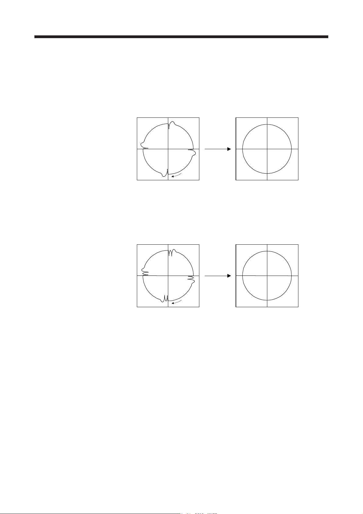
4) Adjusting the lost motion compensation
When protrusions still occur, the compensation is insufficient. Increase the lost motion
compensation by approximately 0.5% until the protrusions are eliminated. When notches occur,
the compensation is excessive. Decrease the lost motion compensation by approximately 0.5%
until the notches are eliminated. Different values can be set as the compensation for each of
when the forward rotation (CCW) switches to the reverse rotation (CW) and when the reverse
rotation (CW) switches to the forward rotation (CCW).
The locus before compensation The locus after compensation
Compensation
Travel
direction
17. APPLICATION OF FUNCTIONS
17 - 67
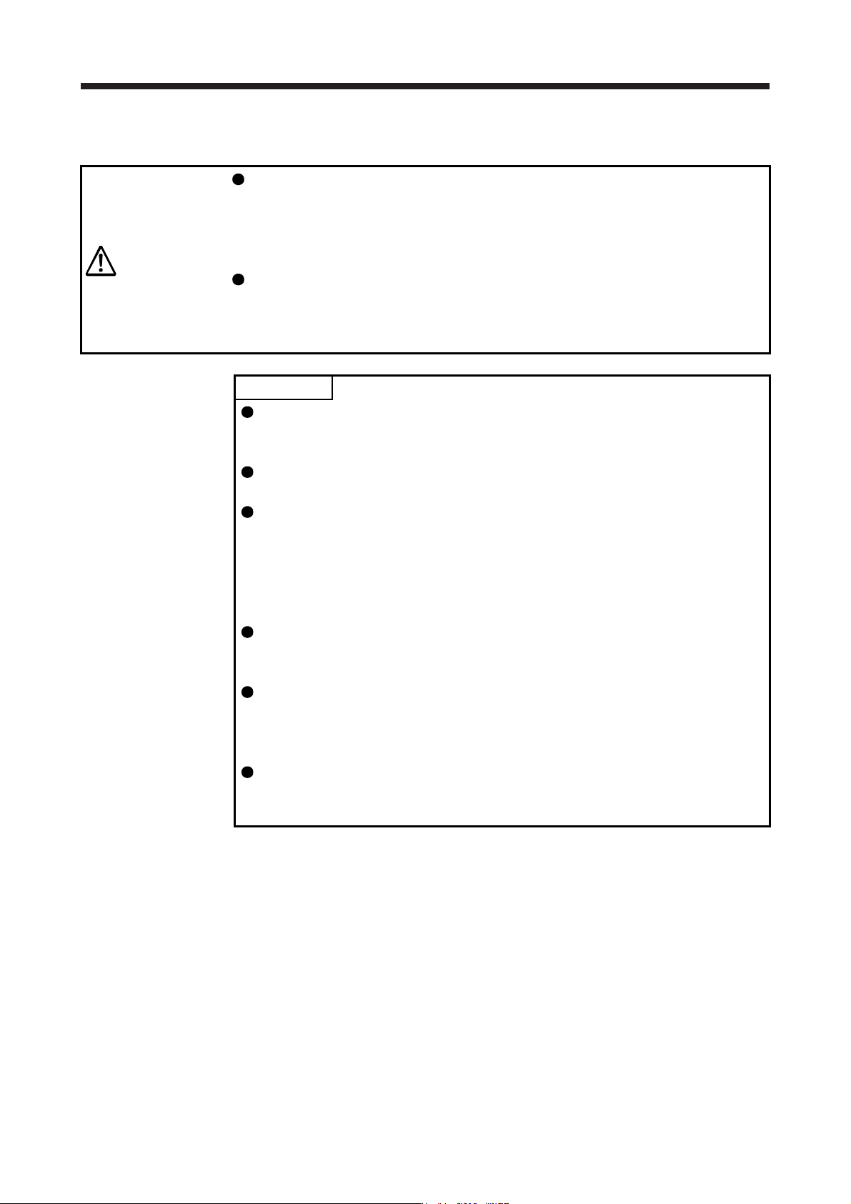
5) Adjusting the lost motion compensation timing
When the machine has low rigidity, the speed loop gain is set lower than the standard setting
value, or the servo motor is rotating at high speed, quadrant projections may occur behind the
quadrant change points. In this case, you can suppress the quadrant projections by delaying the
lost motion compensation timing with [Pr. PX41 Lost motion compensation timing]. Increase the
setting value of [Pr. PX41] from 0 ms (Initial value) by approximately 0.5 ms to adjust the
compensation timing.
Before timing delay compensation After timing delay compensation
Compensation
Travel
direction
6) Adjusting the lost motion compensation non-sensitive band
When the lost motion is compensated twice around a quadrant change point, set [Pr. PX42 Lost
motion compensation non-sensitive band]. Increase the setting value so that the lost motion is not
compensated twice. Setting [Pr. PX42] may change the compensation timing. Adjust the lost
motion compensation timing of (9) (b) 5) in this section.
Before timing delay compensation After timing delay compensation
Compensation
Travel
direction
17. APPLICATION OF FUNCTIONS
17 - 68
17.2 Master-slave operation function
WARNING
Configure the circuit so that all the master and slave axes for the same machine
are stopped by the controller forced stop at the moment of a stop of a master or
slave axis due to such as a servo alarm. When they are not stopped
simultaneously by the controller forced stop, the servo motor may operate
unexpectedly and the machine can be damaged.
All the master and slave axes for the same machine should turn on/off EM1
(Forced stop 1) simultaneously. When EM1 (Forced stop 1) is not turned on/off
simultaneously, the servo motor may operate unexpectedly and the machine can
be damaged.
POINT
The master-slave operation function works only when the forced stop
deceleration function is disabled. When the forced stop deceleration function is
enabled, [AL. 37] will occur.
The master-slave operation function cannot be used with the continuous
operation to torque control.
Use the master-slave operation function with the following controllers. Refer to
the manuals for each servo system controller for compatible software versions,
and other details.
RD77MS/QD77MS_/LD77MS_
R_MTCPU/Q17_DSCPU
Q170MSCPU
When the function is used in vertical axis system, set the same value to the
parameters regarding the dynamic brake and electromagnetic brake to prevent a
drop of axes.
The servo-on command of the master axis and slave axis should be turned
on/off simultaneously. If the servo-on command is turned on only for a slave
axis, torque will not be generated. Therefore, an extreme load will be applied to
the electromagnetic brake of the master axis for using in vertical axis system.
The master-slave operation function is available for servo amplifier with software
version A8 or later. All servo amplifiers used in the same system connected to a
controller should be software version A8 or later.