sh030106u.pdf - 第370页
11. OPT ION S AND P ERI PHER AL EQU IPMENT 11 - 49 (4) Selectio n exa mple of wir es us ed for w iring POINT Sele ction co nditio ns of wi re size are a s follow s. 600 V gra de heat-r esist ant polyv inyl c hloride insu…
11. OPTIONS AND PERIPHERAL EQUIPMENT
11 - 48
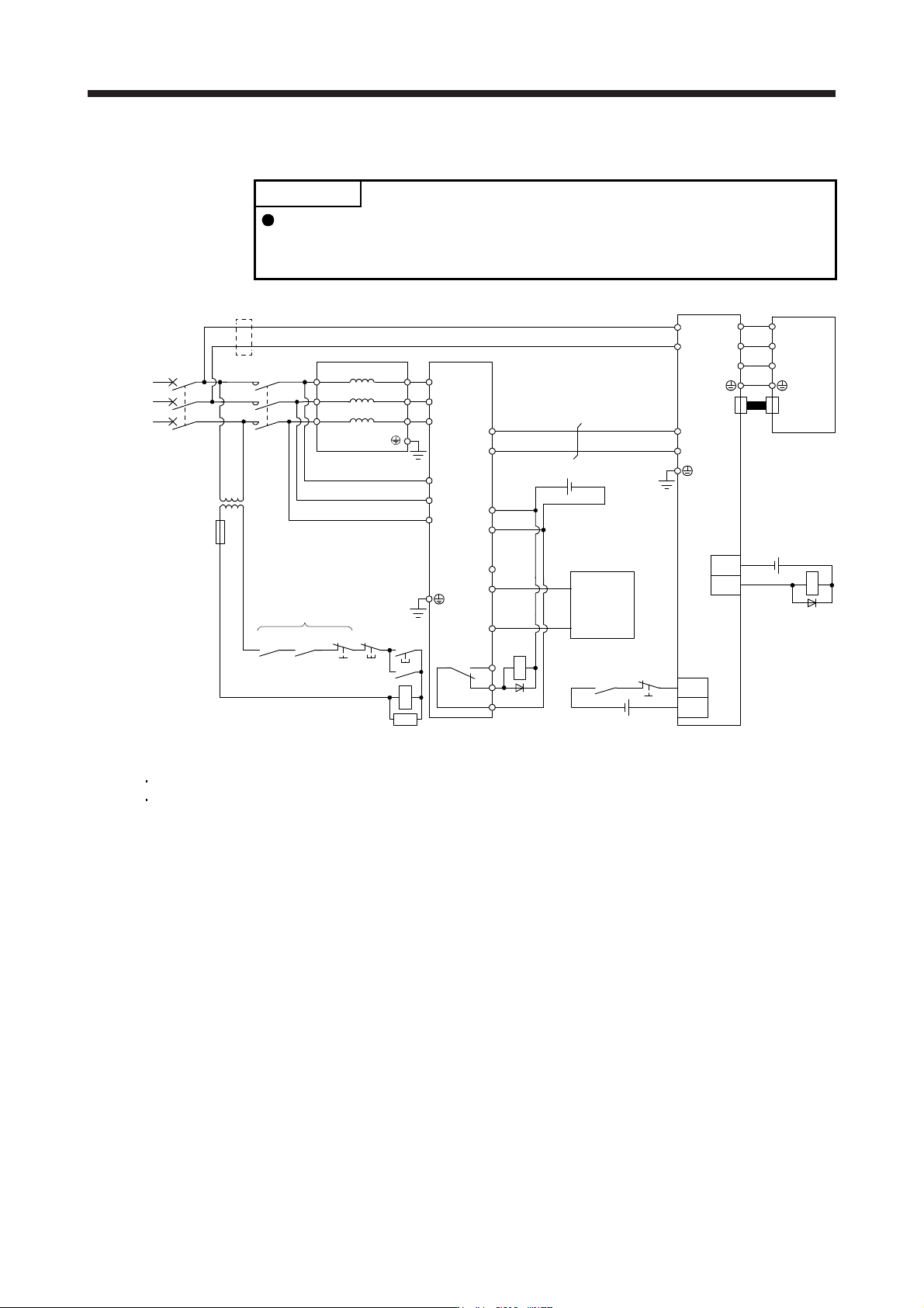
(b) 400 V class
POINT
When using the servo amplifier of 7 kW or less, be sure to disconnect the wiring
of built-in regenerative resistor (3.5 kW or less: P+ and D, 5 kW/7 kW: P+ and
C).
MC
MCCB
R/L11
3-phase
380 V AC to
480 V AC
S/L21
T/L31
S2/L22
R2/L12
T2/L32
FR-CVL-H
MC
RA2RA1
EM1
OFF
ON
(Note 1)
MC
SK
(Note 3)
RA1
EM1
R2/L1
S2/L2
N/L-
(Note 2)
P24
SD
RDYB
RDYA
SE
P/L+
T2/L3
R/L11
S/L21
T/MC1
(Note 1)
L11
L21
P4
N-
U
V
W
(Note 1, 5)
EM1
U
V
W
CN2
FR-CV-H
Servo motor
Servo amplifie
r
Servo system
controller
(Note 4)
(Note 6)
DICOM
B
C
A
RA1
24 V DC (Note 7)
24 V DC (Note 7)
DOCOM
ALM
RA2
24 V DC (Note 7)
Step-down
transformer
Note 1. Configure a sequence that will shut off main circuit power in the following.
An alarm occurred at FR-CV-H or servo amplifier.
EM1
(
Forced stop 1
)
is enabled.
2. For the servo amplifier, confi
g
ure a sequence that will switch the servo-on after the FR-CV-H is read
y
.
3. Configure a sequence that will make a stop with the emergency stop input of the servo system controller if an alarm occurs in
the FR-CV-H. When the servo system controller does not have an emergency stop input, use the forced stop input of the servo
amplifier to make a stop as shown in the dia
g
ram.
4. When usin
g
FR-CV-H, alwa
y
s disconnect wirin
g
between P3 and P4 terminals.
5. Set [Pr. PA04] to "0 0 _ _" to enable EM1
(
Forced stop 1
)
.
6. When wires used for L11 and L21 are thinner than wires used for L1, L2, and L3, use a molded-case circuit breaker.
7. The illustration of the 24 V DC power supply is divided between input signal and output signal for convenience. However, they
can be confi
g
ured b
y
one.
11. OPTIONS AND PERIPHERAL EQUIPMENT
11 - 49
(4) Selection example of wires used for wiring
POINT
Selection conditions of wire size are as follows.
600 V grade heat-resistant polyvinyl chloride insulated wire (HIV wire)
Construction condition: Single wire set in midair
(a) Wire sizes
1) Across P to P4, N to N
The following table indicates the connection wire sizes of the DC power supply (P4, N- terminals)
between the FR-CV and servo amplifier.
Total of servo amplifier capacities [kW] Wire [mm
2
]
1 or less 2 (AWG 14)
2 3.5 (AWG 12)
5 5.5 (AWG 10)
7 8 (AWG 8)
11 14 (AWG 6)
15 22 (AWG 4)
22 50 (AWG 1/0)
27.5 50 (AWG 1/0)
The following table indicates the connection wire sizes of the DC power supply (P4, N- terminals)
between the FR-CV-H and servo amplifier.
Total of servo amplifier capacities [kW] Wire [mm
2
]
2 or less 2 (AWG 14)
3.5 3.5 (AWG 12)
5 5.5 (AWG 10)
7 5.5 (AWG 10)
11 8 (AWG 8)
15 8 (AWG 8)
22 14 (AWG 6)
27.5 22 (AWG 4)
2) Grounding
For grounding, use the wire of the size equal to or greater than that indicated in the following
table, and make it as short as possible.
Power regeneration common
converter
Grounding wire size
[mm
2
]
FR-CV-7.5K to FR-CV-15K 8 (AWG 8)
FR-CV-22K/FR-CV-30K 22 (AWG 4)
FR-CV-37K/FR-CV-55K 38 (AWG 2)
FR-CV-H7.5K to FR-CV-H15K 3.5 (AWG 12)
FR-CV-H22K/FR-CV-H30K 8 (AWG 8)
FR-CV-H37K/FR-CV-H55K 14 (AWG 6)
11. OPTIONS AND PERIPHERAL EQUIPMENT
11 - 50
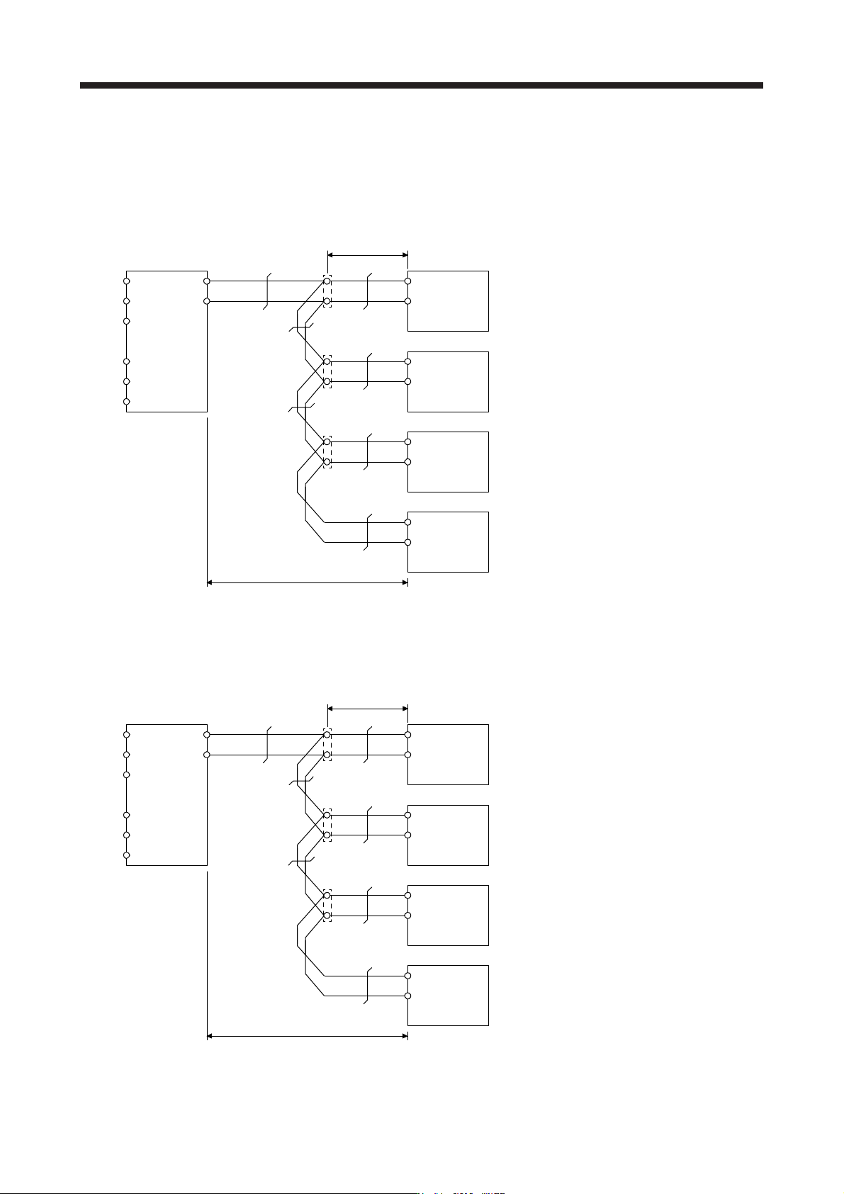
(b) Example of selecting the wire sizes
When connecting multiple servo amplifiers, always use junction terminals for wiring the servo
amplifier terminals P4, N-. Also, connect the servo amplifiers in the order of larger to smaller
capacities.
1) 200 V class
R2/L1
S2/L2
T2/L3
R/L11
S/L21
T/MC1
P/L+
N/L-
P4
N-
50 mm
2
Overall wiring length 5 m or less
First unit:
50 mm
2
assuming that the total of servo amplifier
capacities is 27.5 kW since 15 kW + 7 kW + 3.5 kW
+ 2.0 kW = 27.5 kW.
P4
N-
P4
N-
P4
N-
22 mm
2
8 mm
2
22 mm
2
8 mm
2
3.5 mm
2
5.5 mm
2
Junction terminals
Wire as short as possible.
Second unit:
22 mm
2
assuming that the total of servo amplifier
capacities is 15 kW since 7 kW + 3.5 kW + 2.0 kW =
12.5 kW.
Third unit:
8 mm
2
assuming that the total of servo amplifier
capacities is 7 kW since 3.5 kW + 2.0 kW = 5.5 kW.
Fourth unit:
2 mm
2
assuming that the total of servo amplifier
capacities is 2 kW since 2.0 kW = 2.0 kW.
FR-CV-55K Servo amplifier (15 kW)
Servo amplifier (7 kW)
Servo amplifier (3.5 kW)
Servo amplifier (2 kW)
(Note)
(Note)
(Note)
(Note)
Note. When using the servo amplifier of 7 kW or less, make sure to disconnect the wiring of built-in regenerative resistor (5 kW
or less: P+ and D, 7 kW: P+ and C
)
.
2) 400 V class
R2/L1
S2/L2
T2/L3
R/L11
S/L21
T/MC1
P/L+
N/L-
P4
N-
22 mm
2
Overall wiring length 5 m or less
First unit:
22 mm
2
assuming that the total of servo amplifier
capacities is 27.5 kW since 15 kW + 7 kW + 3.5 kW
+ 2.0 kW = 27.5 kW.
P4
N-
P4
N-
P4
N-
8 mm
2
5.5 mm
2
8 mm
2
5.5 mm
2
2 mm
2
3.5 mm
2
Junction terminals
Wire as short as possible.
Second unit:
8 mm
2
assuming that the total of servo amplifier
capacities is 15 kW since 7 kW + 3.5 kW + 2.0 kW =
12.5 kW.
Third unit:
5.5 mm
2
assuming that the total of servo amplifier
capacities is 7 kW since 3.5 kW + 2.0 kW = 5.5 kW.
Fourth unit:
2 mm
2
assuming that the total of servo amplifier
capacities is 2 kW since 2.0 kW = 2.0 kW.
FR-CV-H55K Servo amplifier (15 kW)
Servo amplifier (7 kW)
Servo amplifier (3.5 kW)
Servo amplifier (2 kW)
(Note)
(Note)
(Note)
(Note)
Note. When using the servo amplifier of 7 kW or less, make sure to disconnect the wiring of built-in regenerative resistor (5 kW
o
r
less: P+ and D, 7 kW: P+ and C
)
.