sh030106u.pdf - 第621页
17. APPLICATIO N OF FUNCTIONS 17 - 70 Eigh t maste r axes can be set at most pe r one syst em of SSCNET I II/H. The m aximum number o f slave axes to e ach mast er axis is not limited. H owever, the t otal num ber of the…
17. APPLICATION OF FUNCTIONS
17 - 69
(1) Summary
The master-slave operation function transmits a master axis torque to slave axes using driver
communication and the torque as a command drives slave axes by torque control.
Transmission of torque data from the master axis to slave axes is via SSCNET III/H. Additional wiring is
not required.
(2) System configuration
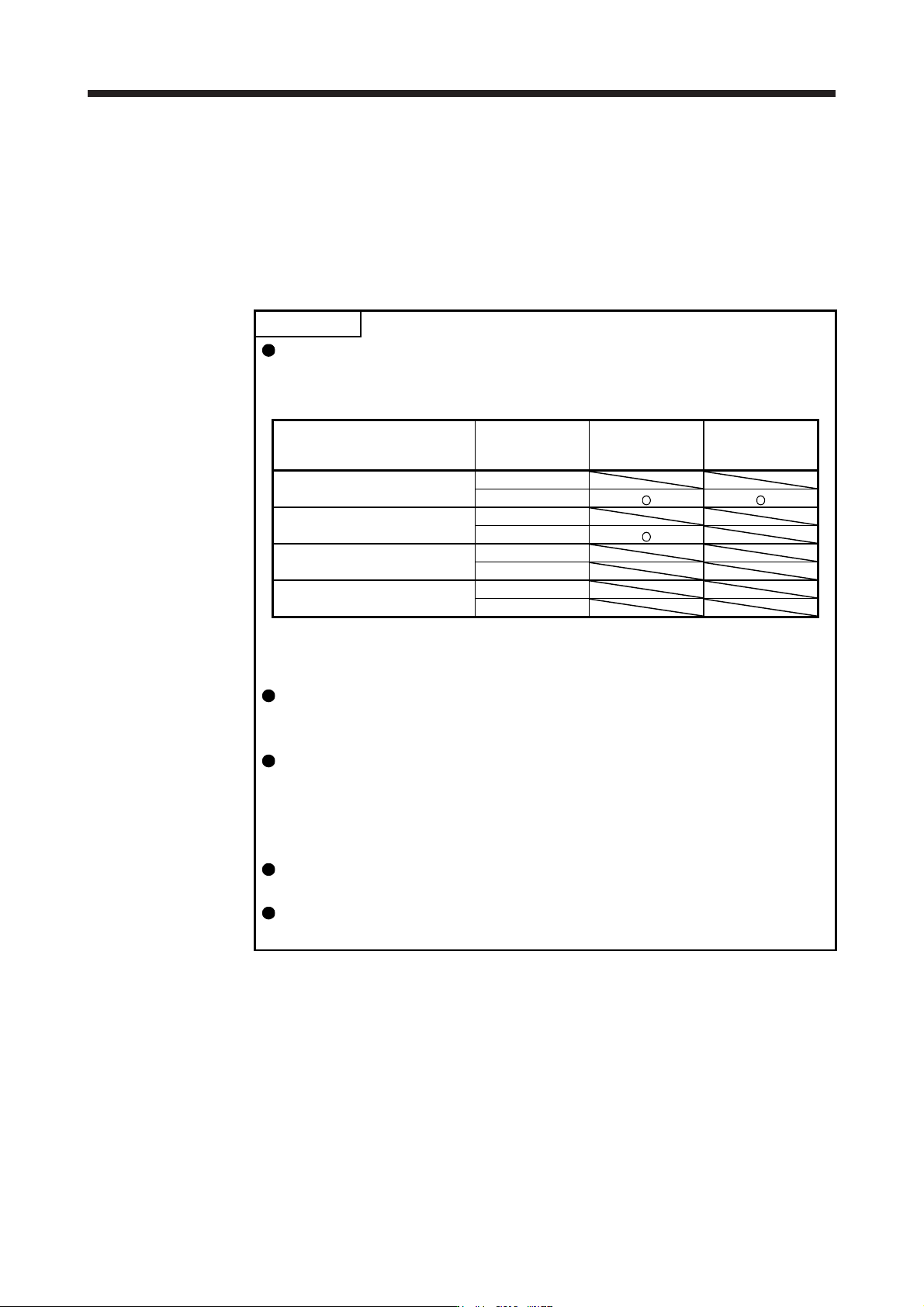
POINT
The control modes compatible with the master-slave operation function are as
follows.
Master-slave operation function compatibility table
Control mode
Forced stop
deceleration
function
Master axis (Note) Slave axis (Note)
Standard control mode
Enabled
Disabled
Fully closed loop control mode
Enabled
Disabled
Linear servo motor control mode
Enabled
Disabled
DD motor control mode
Enabled
Disabled
Note. When a setting for the master-slave operation is set to an axis which is not compatible with the
maste
r
-slave operation function, [AL. 37] will occur.
The master axis and slave axis are recommended to use for a linked condition
on a mechanical constitution. When they are not linked, they can reach a speed
limit level. Doing so may cause [AL. 31 Overspeed].
The slave axes use the control command from the master axis. Therefore, the
controller mainly controls parameter settings, servo-on command, acquisition of
monitor information from a servo amplifier, etc. The commands regarding
absolute positioning such as setting absolute position detection and requiring
home position setting from the controller to slave axes must not be made.
Configure the circuit so that all the master and slave axes are stopped at the
moment of a stop of a master or slave axis due to such as an alarm.
When the STO signal of a servo amplifier is used, the master axis and slave axis
should be turned off simultaneously.
17. APPLICATION OF FUNCTIONS
17 - 70
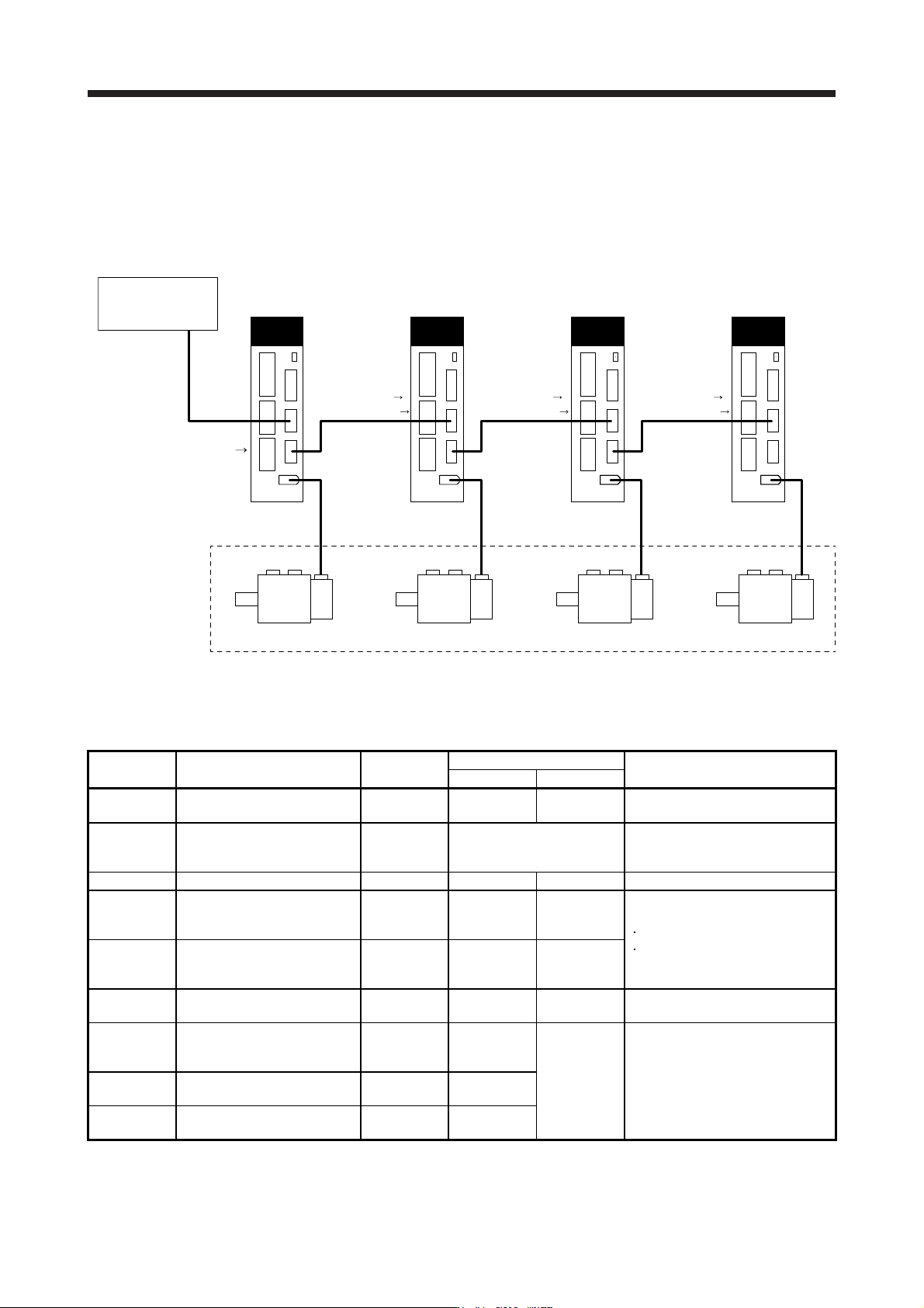
Eight master axes can be set at most per one system of SSCNET III/H. The maximum number of slave
axes to each master axis is not limited. However, the total number of the master and slave axes should
be the maximum number of the servo amplifiers at most. In addition, when an SSCNET III/H
communication shut-off occurs due to malfunction of a servo amplifier, the malfunctioning axis and later
axis cannot be communicated. Therefore, the first amplifier from the controller via SSCNET III/H cable
should be master axis.
Master axis
MR-J4-_B_(-RJ)
CN2 CN2 CN2 CN2
Slave axis 1
MR-J4-_B_(-RJ)
Slave axis 2
MR-J4-_B_(-RJ)
Slave axis 3
MR-J4-_B_(-RJ)
These are for the
same machine.
Controller
Position
command
[Driver communication]
Torque command
Speed limit command
[Driver communication] [Driver communication]
Torque command
Speed limit command
Torque command
Speed limit command
(3) Parameter setting for the master-slave operation function
To use the master-slave operation function, the following parameter settings are necessary. For details
of the parameters, refer to section 5.2.1 and 5.2.4.
No. Name Initial value
Setting value
Setting
Master axis Slave axis
PA04
Forced stop deceleration
function selection
2000 0 _ _ _ 0 _ _ _
Used to disable the forced stop
deceleration function.
PA14
Rotation direction
selection/travel direction
selection
0 Refer to section 5.2.1.
Used to set a torque generation
direction.
PD15 (Note) Driver communication setting 0000 0001 0010 Master and slave setting
PD16 (Note)
Driver communication setting -
Master - Transmit data
selection 1
0000 0038 0000
Communication data from master to
slave
Torque command
Speed limit value
PD17 (Note)
Driver communication setting -
Master - Transmit data
selection 2
0000 003A 0000
PD20 (Note)
Master axis No. selection 1 for
slave
0 0
Master axis
No.
Master axis No. of transmitting data
PD30
Master-slave operation -
Torque command coefficient on
slave
0 0
Refer to
section 5.2.4.
Ratio of torque command of slave
axis, ratio of speed limit value, and
setting of speed limit minimum value
PD31
Master-slave operation - Speed
limit coefficient on slave
0 0
PD32
Master-slave operation - Speed
limit adjusted value on slave
0 0
Note.
A
lwa
y
s set this with parameters of the controller.
17. APPLICATION OF FUNCTIONS
17 - 71
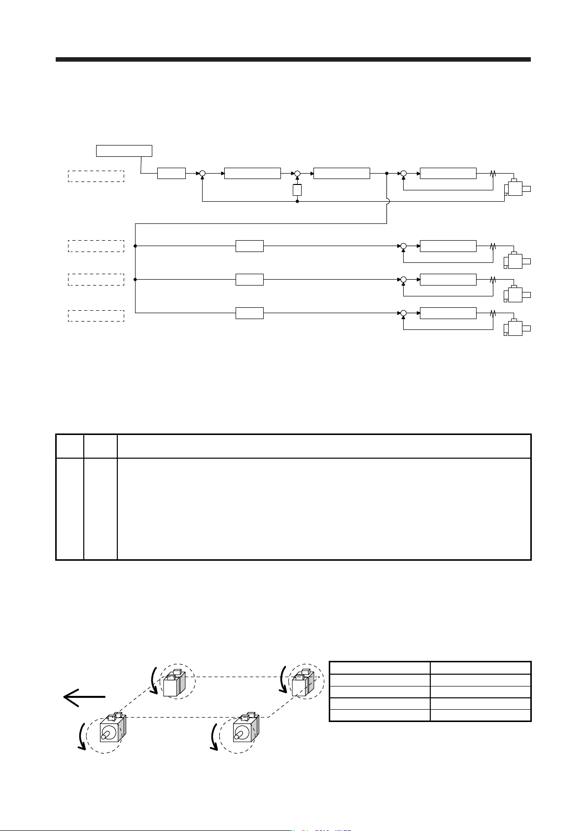
(4) Rotation direction setting
Rotation directions can be different among a controller command, master axis, and slave axes. To align
the directions, set [Pr. PA14] referring to (4) in this section. Not doing so can cause such as an overload
due to a reverse direction torque against machine system rotation direction.
Controller
Master axis
Slave axis 1
Slave axis 2
Slave axis 3
Position control Speed control
S
Current control
+
--
Current control
Current control
Current control
[Pr. PA14]
0 or 1 (Note)
[Pr. PA14]
0 or 1 (Note)
[Pr. PA14]
0 or 1 (Note)
[Pr. PA14]
0 or 1 (Note)
+
-
+
-
+
-
+
-
+
POL
POL
POL
POL
Note. Settin
g
"1" will reverse the polarit
y
.
Fig. 17.3 Rotation direction setting of master and slave axes with torque command method for an
example of one master axis and three slave axes
Table 17.11 Rotation direction setting parameter
No. Symbol Name and function
PA14 *POL
Rotation direction selection
1. For master axis
Select a servo motor rotation direction of master axis to SSCNET controller command.
0: Servo motor CCW rotation in positioning address increase direction
1: Servo motor CW rotation in positioning address increase direction
2. For slave axis
Select servo motor rotation direction to a command from master axis.
0: Torque command polarity from master axis
1: Reverse of torque command polarity from master axis
The following shows a setting example of rotation direction for a platform truck with one master axis and
three slave axes.
To set a rotation direction of the servo motor according to the moving direction, set the torque command
polarity to the slave axis 1 the same as that to the master axis, and set the opposite polarity to the slave
axis 2 and slave axis 3 from the master axis.
Slave axis 2
Slave axis 1Master axis
Slave axis 3
Moving direction
CW
CCW CCW
CW
[Pr. PA14] setting
Axis [Pr. PA14]
Master axis 0
Slave axis 1 0
Slave axis 2 1
Slave axis 3 1