sh030106u.pdf - 第660页
APPENDIX App. - 29 Setting value Output item Des cription Setting value Output item Desc ription 0A Feedback pos ition (No te 1, 2, 3 ) (±10 V/1 M pulse) 1 [Mpulse] CW direction CCW direction 1 [Mpulse ] 0 10 [V] -10 [V]…
APPENDIX
App. - 28
App. 10.2 Setting
POINT
When you use a linear servo motor, replace the following words in the left to the
words in the right.
(servo motor) speed →(linear servo motor) speed
CCW direction →Positive direction
CW direction →Negative direction
Torque →Thrust
The servo amplifier is factory-set to output the servo motor speed to MO1 (Analog monitor 1) and the
torque to MO2 (Analog monitor 2). The setting can be changed as listed below by setting the [Pr. PC09]
and [Pr. PC10] value.
Refer to (3) for the detection point.
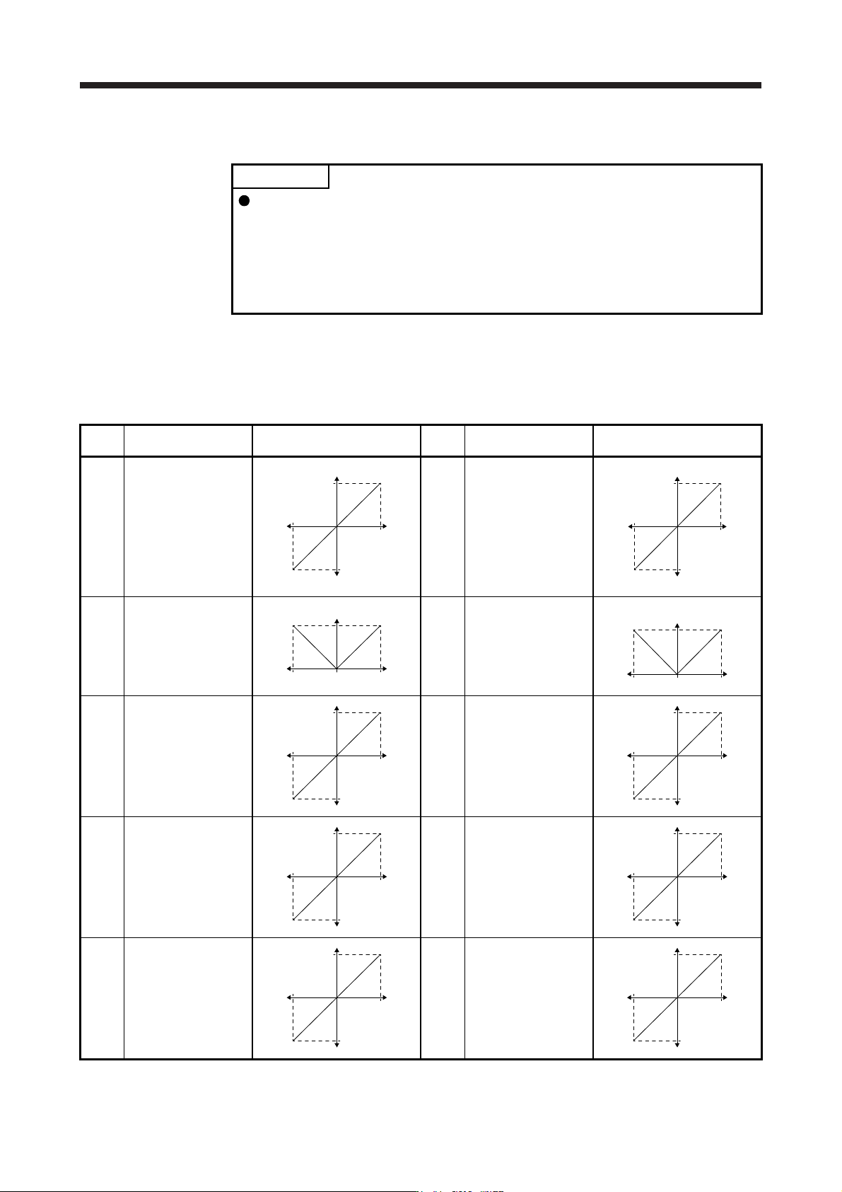
Setting
value
Output item Description
Setting
value
Output item Description
00 Servo motor speed/
Linear servo motor
speed
Maximum speed
CW direction
CCW direction
Maximum speed
0
8 [V]
-8 [V]
01 Torque/Thrust (Note 8)
Maximum torqu
e
Power running i
n
CW direction
Power running i
n
CCW direction
Maximum torque
0
8 [V]
-8 [V]
02 Servo motor speed/
Linear servo motor
speed
Maximum speed
CW direction CCW direction
Maximum speed 0
8 [V]
03 Torque/Thrust (Note 8)
Maximum torqu
e
Power running i
n
CW direction
Power running i
n
CCW direction
Maximum torque 0
8 [V]
04
Current command
(Note 8)
Maximum current command
(Maximum torque command)
CW directio
n
CCW directio
n
Maximum current comman
d
(
Maximum torque comman
d
0
8 [V]
-8 [V]
05 Speed command
Maximum speed
CW directio
n
CCW directio
n
Maximum speed
0
8 [V]
-8 [V]
06
Servo motor-side droop
pulses
(Note 1, 3, 5, 6)
(±10 V/100 pulses)
100 [pulse]
CW directio
n
CCW directio
n
100 [pulse
]
0
10 [V]
-10 [V]
07
Servo motor-side droop
pulses
(Note 1, 3, 5, 6)
(±10 V/1000 pulses)
1000 [pulse]
CW directio
n
CCW directio
n
1000 [pulse
]
0
10 [V]
-10 [V]
08
Servo motor-side droop
pulses
(Note 1, 3, 5, 6)
(±10 V/10000 pulses)
10000 [pulse]
CW directio
n
CCW directio
n
10000 [pulse
]
0
10 [V]
-10 [V]
09
Servo motor-side droop
pulses
(Note 1, 3, 5, 6)
(±10 V/100000 pulses)
100000 [pulse]
CW directio
n
CCW directio
n
100000 [pulse
]
0
10 [V]
-10 [V]
APPENDIX
App. - 29
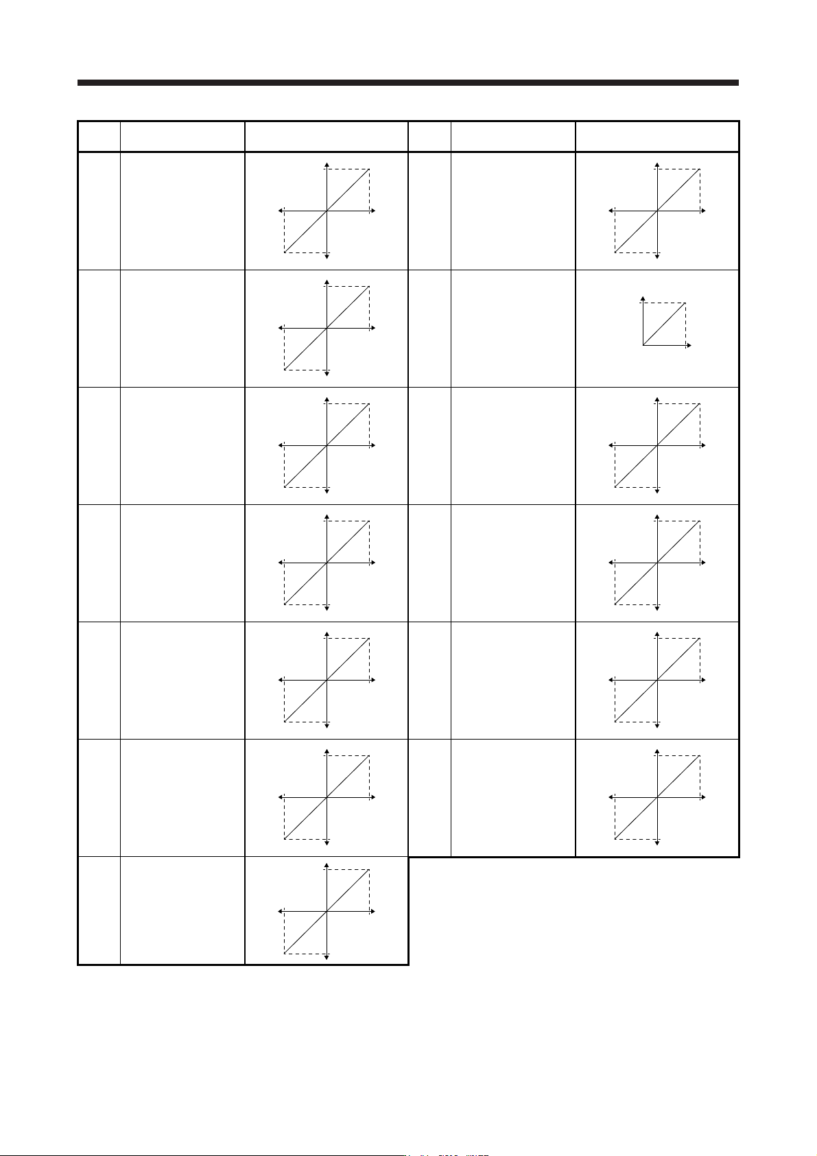
Setting
value
Output item Description
Setting
value
Output item Description
0A
Feedback position
(Note 1, 2, 3)
(±10 V/1 Mpulse)
1 [Mpulse]
CW direction
CCW direction
1 [Mpulse
]
0
10 [V]
-10 [V]
0B
Feedback position
(Note 1, 2, 3)
(±10 V/10 Mpulse)
10 [Mpulse]
CW direction
CCW direction
10 [Mpulse
]
0
10 [V]
-10 [V]
0C
Feedback position
(Note 1, 2, 3)
(±10 V/100 Mpulse)
100 [Mpulse]
CW direction
CCW direction
100 [Mpulse
]
0
10 [V]
-10 [V]
0D Bus voltage (Note 7)
400 [V]
0
8 [V]
0E
Speed command 2
(Note 3)
Maximum speed
CW direction
CCW direction
Maximum speed
0
8 [V]
-8 [V]
10
Load-side droop pulses
(Note 3, 4, 5, 6)
(±10 V/100 pulses)
100 [pulse]
CW direction
CCW direction
100 [pulse
]
0
10 [V]
-10 [V]
11
Load-side droop pulses
(Note 3, 4, 5, 6)
(±10 V/1000 pulses)
1000 [pulse]
CW direction
CCW direction
1000 [pulse
]
0
10 [V]
-10 [V]
12
Load-side droop pulses
(Note 3, 4, 5, 6)
(±10 V/10000 pulses)
10000 [pulse]
CW direction
CCW direction
10000 [pulse
]
0
10 [V]
-10 [V]
13
Load-side droop pulses
(Note 3, 4, 5, 6)
(±10 V/100000 pulses)
100000 [pulse]
CW direction
CCW direction
100000 [pulse
]
0
10 [V]
-10 [V]
14
Load-side droop pulses
(Note 3, 4, 5, 6)
(±10 V/1 Mpulse)
1 [Mpulse]
CW direction
CCW direction
1 [Mpulse
]
0
10 [V]
-10 [V]
15
Motor-side/load-side
position deviation
(Note 3, 4, 5, 6)
(±10 V/100000 pulses)
100000 [pulse]
CW direction
CCW direction
100000 [pulse
]
0
10 [V]
-10 [V]
16
Servo motor-side/load-
side speed deviation
(Note 4)
Maximum speed
CW direction
CCW direction
Maximum speed
0
8 [V]
-8 [V]
17
Internal temperature of
encoder
(±10 V/±128 °C)
128 [°C]
-
128 [°C]
0
10 [V]
-10 [V]
APPENDIX
App. - 30
Note 1. Encoder pulse unit.
2.
A
vailable in position control mode
3. This cannot be used in the torque control mode.
4. This can be used with MR Confi
g
urator2 with software version 1.19V or later.
5. This cannot be used in the speed control mode.
6. Output in the load-side encoder unit for the fully closed loop control. Output in the servo motor encoder unit for the semi closed
loop control.
7. For 400 V class servo amplifier, the bus volta
g
e becomes +8 V/800 V.
8. For details on the maximum current command
(
maximum torque
)
for ±8 V, refer to app. 10.4 for details.
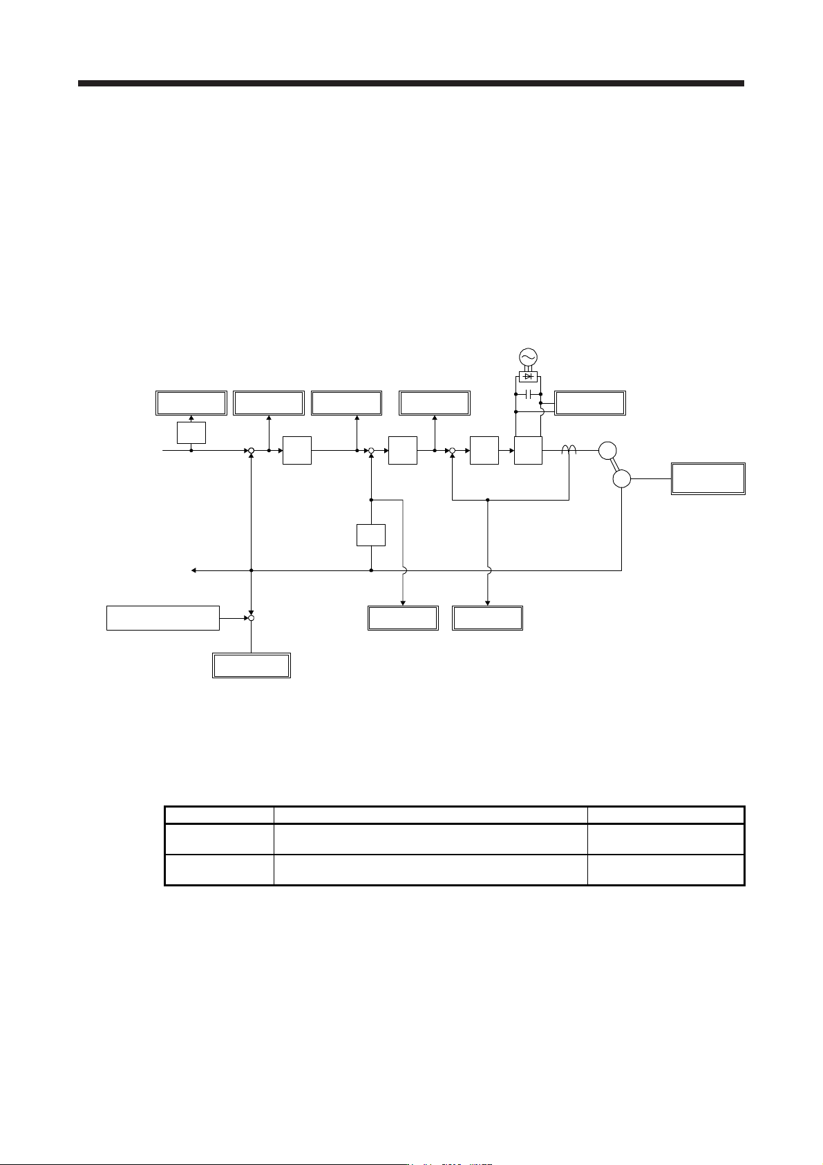
App. 10.3 Analog monitor block diagram
App. 10.3.1 Semi closed loop control
Droop pulses
Speed
command
Position
control
Speed
control
PWM
Current
control
Current
command
Bus voltage
Speed
command
Current
encoder
+
Servo motor
Encoder
Current feedback
Position feedback
M
Position command
received from a
servo system
controller
Position feedback data
returned to a servo
system controller
Differen-
tiation
Differen-
tiation
Feedback position
standard position (Note)
Feedback
position
+
-
Internal
temperature
of encoder
Servo motor
speed
Torque
+
+
-
-
+
-
Speed
command 2
Note. The feedback position is output based on the position data passed between servo system controller and servo amplifier. [Pr.
PC13] and [Pr. PC14] can set up the standard position of feedback position that is output to analog monitor in order to adjust the
output ran
g
e of feedback position. The settin
g
ran
g
e is between -9999 pulses and 9999 pulses.
Standard position of feedback position = [Pr. PC14] setting value × 10000 + [Pr. PC13] setting value
Parameter Description Setting range
PC13
Sets the lower-order four digits of the standard position of
feedback position
-9999 to 9999 [pulse]
PC14
Sets the higher-order four digits of the standard position of
feedback position
-9999 to 9999 [10000 pulses]