sh030106u.pdf - 第179页
5. PARAMETE RS 5 - 34 No. Sym bol Name and function Initial value [unit] Setting range PB58 VRF23B Vibrati on suppression cont rol 2 - Vibration frequen cy damping after gain switc hing Set a dam ping of the vibrat ion f…

5. PARAMETERS
5 - 33
No. Symbol Name and function
Initial
value
[unit]
Setting
range
PB53 VRF22 Vibration suppression control 2 - Resonance frequency
Set the resonance frequency for vibration suppression control 2 to suppress low-frequency
machine vibration.
To enable the setting value, set "Vibration suppression mode selection" to "3 inertia mode (_ _
_ 1)" in [Pr. PA24].
When "Vibration suppression control 2 tuning mode selection" is set to "Automatic setting (_ _
1 _)" in [Pr. PB02], this parameter will be set automatically. When "Manual setting (_ _ 2 _)" is
selected, the setting written to the parameter is used.
The setting range of this parameter varies, depending on the value in [Pr. PB07]. If a value out
of the range is set, the vibration suppression control will be disabled. Refer to section 7.1.5 for
details.
100.0
[Hz]
0.1 to
300.0
PB54 VRF23 Vibration suppression control 2 - Vibration frequency damping
Set a damping of the vibration frequency for vibration suppression control 2 to suppress low-
frequency machine vibration.
To enable the setting value, set "Vibration suppression mode selection" to "3 inertia mode (_ _
_ 1)" in [Pr. PA24].
When "Vibration suppression control 2 tuning mode selection" is set to "Automatic setting (_ _
1 _)" in [Pr. PB02], this parameter will be set automatically. When "Manual setting (_ _ 2 _)" is
selected, the setting written to the parameter is used. Refer to section 7.1.5 for details.
0.00
0.00 to
0.30
PB55 VRF24 Vibration suppression control 2 - Resonance frequency damping
Set a damping of the resonance frequency for vibration suppression control 2 to suppress low-
frequency machine vibration.
To enable the setting value, set "Vibration suppression mode selection" to "3 inertia mode (_ _
_ 1)" in [Pr. PA24].
When "Vibration suppression control 2 tuning mode selection" is set to "Automatic setting (_ _
1 _)" in [Pr. PB02], this parameter will be set automatically. When "Manual setting (_ _ 2 _)" is
selected, the setting written to the parameter is used. Refer to section 7.1.5 for details.
0.00
0.00 to
0.30
PB56 VRF21B Vibration suppression control 2 - Vibration frequency after gain switching
Set the vibration frequency for vibration suppression control 2 when the gain switching is
enabled.
When you set a value less than 0.1 Hz, the value will be the same as [Pr. PB52].
To enable this, select "3 inertia mode (_ _ _ 1)" of "Vibration suppression mode selection" in
[Pr. PA24].
This parameter will be enabled only when the following conditions are fulfilled.
"Gain adjustment mode selection" in [Pr. PA08] is "Manual mode (_ _ _ 3)".
"Vibration suppression control 2 tuning mode selection" in [Pr. PB02] is "Manual setting (_ _
2 _)".
"Gain switching selection" in [Pr. PB26] is "Control command from controller is enabled (_ _
_ 1)".
Switching during driving may cause a shock. Be sure to switch them after the servo motor or
linear servo motor stops.
0.0
[Hz]
0.0 to
300.0
PB57 VRF22B Vibration suppression control 2 - Resonance frequency after gain switching
Set the resonance frequency for vibration suppression control 2 when the gain switching is
enabled.
When you set a value less than 0.1 Hz, the value will be the same as [Pr. PB53].
To enable this, select "3 inertia mode (_ _ _ 1)" of "Vibration suppression mode selection" in
[Pr. PA24].
This parameter will be enabled only when the following conditions are fulfilled.
"Gain adjustment mode selection" in [Pr. PA08] is "Manual mode (_ _ _ 3)".
"Vibration suppression control 2 tuning mode selection" in [Pr. PB02] is "Manual setting (_ _
2 _)".
"Gain switching selection" in [Pr. PB26] is "Control command from controller is enabled (_ _
_ 1)".
Switching during driving may cause a shock. Be sure to switch them after the servo motor or
linear servo motor stops.
0.0
[Hz]
0.0 to
300.0

5. PARAMETERS
5 - 34
No. Symbol Name and function
Initial
value
[unit]
Setting
range
PB58 VRF23B Vibration suppression control 2 - Vibration frequency damping after gain switching
Set a damping of the vibration frequency for vibration suppression control 2 when the gain
switching is enabled.
To enable this, select "3 inertia mode (_ _ _ 1)" of "Vibration suppression mode selection" in
[Pr. PA24].
This parameter will be enabled only when the following conditions are fulfilled.
"Gain adjustment mode selection" in [Pr. PA08] is "Manual mode (_ _ _ 3)".
"Vibration suppression control 2 tuning mode selection" in [Pr. PB02] is "Manual setting (_ _
2 _)".
"Gain switching selection" in [Pr. PB26] is "Control command from controller is enabled (_ _
_ 1)".
Switching during driving may cause a shock. Be sure to switch them after the servo motor or
linear servo motor stops.
0.00
0.00 to
0.30
PB59 VRF24B Vibration suppression control 2 - Resonance frequency damping after gain switching
Set a damping of the resonance frequency for vibration suppression control 2 when the gain
switching is enabled.
To enable this, select "3 inertia mode (_ _ _ 1)" of "Vibration suppression mode selection" in
[Pr. PA24].
This parameter will be enabled only when the following conditions are fulfilled.
"Gain adjustment mode selection" in [Pr. PA08] is "Manual mode (_ _ _ 3)".
"Vibration suppression control 2 tuning mode selection" in [Pr. PB02] is "Manual setting (_ _
2 _)".
"Gain switching selection" in [Pr. PB26] is "Control command from controller is enabled (_ _
_ 1)".
Switching during driving may cause a shock. Be sure to switch them after the servo motor or
linear servo motor stops.
0.00
0.00 to
0.30
PB60 PG1B Model loop gain after gain switching
Set the model loop gain when the gain switching is enabled.
When you set a value less than 1.0 rad/s, the value will be the same as [Pr. PB07].
This parameter will be enabled only when the following conditions are fulfilled.
"Gain adjustment mode selection" in [Pr. PA08] is "Manual mode (_ _ _ 3)".
"Gain switching selection" in [Pr. PB26] is "Control command from controller is enabled (_ _
_ 1)".
Switching during driving may cause a shock. Be sure to switch them after the servo motor or
linear servo motor stops.
0.0
[rad/s]
0.0 to
2000.0
5. PARAMETERS
5 - 35
5.2.3 Extension setting parameters ([Pr. PC_ _ ])
No. Symbol Name and function
Initial
value
[unit]
Setting
range
PC01 ERZ Error excessive alarm level
Set an error excessive alarm level.
Set this per rev. for rotary servo motors and direct drive motors. Setting "0" will be 3 rev.
Setting over 200 rev will be clamped with 200 rev.
Set this per mm for linear servo motors. Setting "0" will be 100 mm.
Refer to app. 6 for the adjustment method.
0
[rev]/
[mm]
(Note)
0 to
1000
Note. Setting can be changed in [Pr. PC06].
PC02 MBR Electromagnetic brake sequence output
This is used to set the delay time between MBR (Electromagnetic brake interlock) and the
base drive circuit is shut-off. For the timing chart of when the servo motor with an
electromagnetic brake is used, refer to section 3.10.2.
0
[ms]
0 to
1000
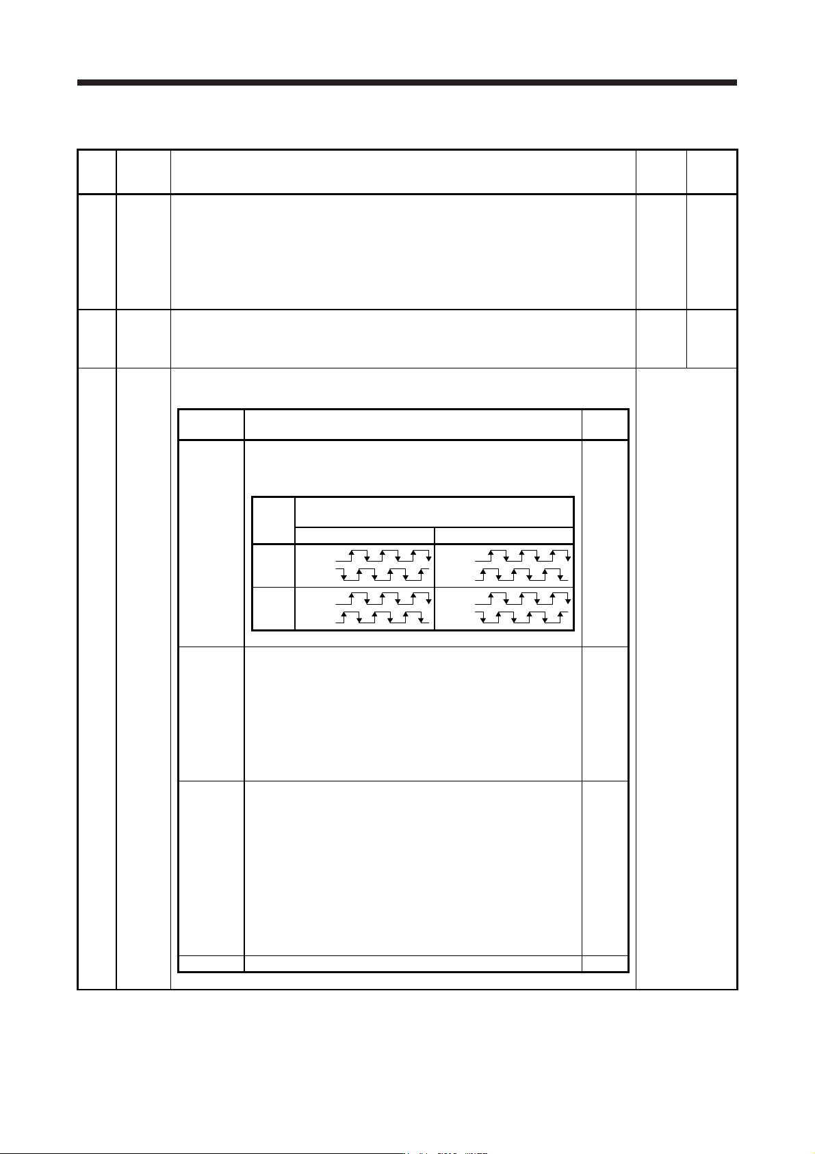
PC03 *ENRS Encoder output pulse selection
This is used to select the encoder pulse direction and encoder output pulse setting.
Refer to the
"Name and
function" column.
Setting
digit
Explanation
Initial
value
_ _ _ x Encoder output pulse phase selection
0: Increasing A-phase 90° in CCW or positive direction
1: Increasing A-phase 90° in CW or negative direction
0h
Setting
value
Servo motor rotation direction/
linear servo motor travel direction
CCW or positive direction CW or negative direction
0
A-phase
B-phase
A
-phase
B-phase
1
A-phase
B-phase
A
-phase
B-phase
_ _ x _ Encoder output pulse setting selection
Refer to app. 17 for details.
0: Output pulse setting
1: Division ratio setting
3: A-phase/B-phase pulse electronic gear setting
4: A/B-phase pulse through output setting
Depending on the servo motor stop position, the encoder output
pulse may turn on and off repeatedly even if the servo motor is
stopped.
0h
_ x _ _ Selection of the encoders for encoder output pulse
This is used for selecting an encoder for servo amplifier output.
0: Servo motor encoder
1: Load-side encoder
When "_ 1 0 _" is set to this parameter, [AL. 37 Parameter error]
will occur.
Selecting "1" in other than fully closed loop system or standard
control system (scale measurement function: enabled) triggers [AL.
37 Parameter error].
Depending on the servo motor stop position, the encoder output
pulse may turn on and off repeatedly even if the servo motor is
stopped.
0h
x _ _ _ For manufacturer setting 0h