sh030106u.pdf - 第549页
16. FULLY CLOSE D L OOP SYS TEM 16 - 24 16. 3.8 Abso lute po sitio n detect ion syste m und er full y clo sed lo op system An absol ute type l inear e ncoder is neces sary to config ure an ab solut e pos ition detecti on…
16. FULLY CLOSED LOOP SYSTEM
16 - 23
(b) Position deviation error detection
Set [Pr. PE03] to "_ _ _ 2" to enable the position deviation error detection.
Position deviation error detectio
n
2
[Pr. PE03]
Comparing the servo motor-side feedback position (2)) and load-side feedback position (4)), if the
deviation is not less than the set value (1 kpulses to 20000 kpulses) of [Pr. PE07 Fully closed loop
control position deviation error detection level], the function generates [AL. 42.1 Servo control error
by position deviation] and stops. The initial value of [Pr. PE07] is 100 kpulses. Change the set value
as required.
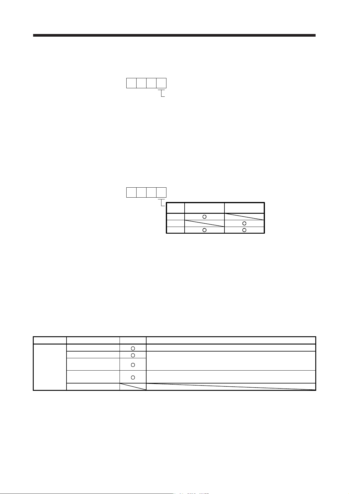
(c) Detecting multiple deviation errors
When setting [Pr. PE03] as shown below, multiple deviation errors can be detected. For the error
detection method, refer to (2) (a), (b) in this section.
[Pr. PE03]
Setting
value
Speed deviation
error detection
Position deviation
error detection
1
2
3
16.3.5 Auto tuning function
Refer to section 6.3 for the auto tuning function.
16.3.6 Machine analyzer function
Refer to Help of MR Configurator2 for the machine analyzer function of MR Configurator2.
16.3.7 Test operation mode
Test operation mode is enabled by MR Configurator2.
For details on the test operation mode, refer to section 4.5.
Function Item Usability Remark
Test
operation
mode
JOG operation
It drives in the load-side encoder resolution unit
Positioning operation
The fully closed loop system is operated in the load-side encoder resolution
unit.
For details, refer to section 4.5.1 (1) (c).
Program operation
Output signal (DO)
forced output
Refer to section 4.5.1 (1) (d).
Motor-less operation

16. FULLY CLOSED LOOP SYSTEM
16 - 24
16.3.8 Absolute position detection system under fully closed loop system
An absolute type linear encoder is necessary to configure an absolute position detection system under fully
closed loop control using a linear encoder. In this case, the encoder battery need not be installed to the
servo amplifier. When an rotary encoder is used, an absolute position detection system can be configured by
installing the encoder battery to the servo amplifier. In this case, the battery life will be shorter because the
power consumption is increased as the power is supplied to the two encoders of motor side and load side.
If using an absolute position detection system with a linear encoder, enable the system with [Pr. PA03
Absolute position detection system], and use this servo with the following restrictions.
(1) Using conditions
(a) Use an absolute type linear encoder with the load-side encoder.
(b) Set [Pr. PA01] to "_ _ 1 _", and [Pr. PE01] to "_ _ _ 0".
(2) Absolute position detection range using encoder
Encoder type Absolute position detection enabled range
Linear encoder
(Serial Interface)
Movable distance range of linear encoder (within 32-bit absolute position data)
(3) Alarm detection
The absolute position-related alarm ([AL. 25]) and warnings (AL. 92] and [AL. 9F]) are not detected.
16. FULLY CLOSED LOOP SYSTEM
16 - 25
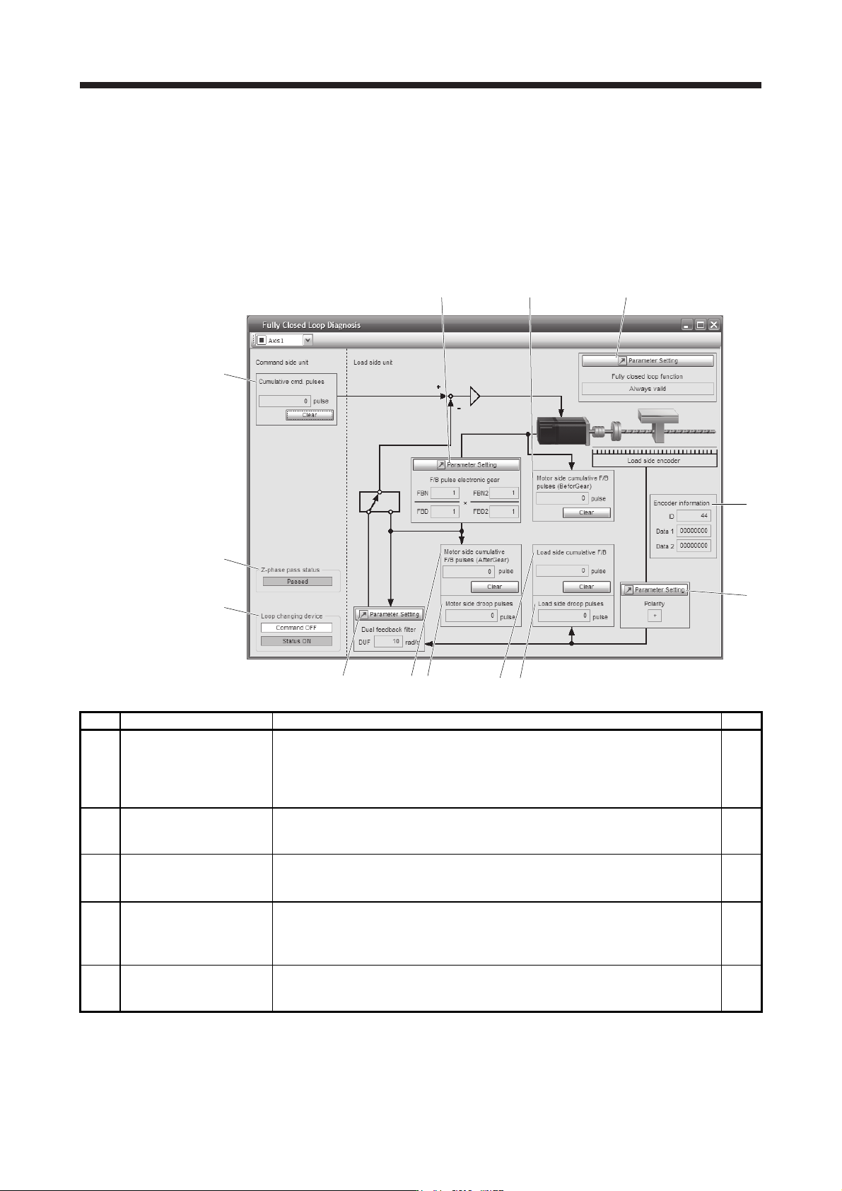
16.3.9 About MR Configurator2
Using MR Configurator2 can confirm if the parameter setting is normal or if the servo motor and the load-side
encoder operate properly.
This section explains the fully closed diagnosis screen.
Click "Monitor start" to constantly read the monitor display items from the servo amplifier.
Then, click "Monitor stop" to stop reading. Click "Parameter read" to read the parameter items from the servo
amplifier, and then click "Parameter write" to write them.
f)
a)
c)
k)
b)
i)
h)
g)
d) e)
j)
m)
l)
Symbol Name Explanation Unit
a)
Motor side cumu. feedback
pulses (after gear)
Feedback pulses from the servo motor encoder are counted and displayed. (load-side
encoder unit)
When the set value exceeds 999999999, it starts with 0.
Click "Clear" to reset the value to 0.
The "-" symbol is indicated for reverse.
pulse
b) Motor side droop pulses
Droop pulses of the deviation counter between a servo motor-side position and a
command are displayed.
The "-" symbol is indicated for reverse.
pulse
c) Cumu. Com. pulses Position command input pulses are counted and displayed.
Click "Clear" to reset the value to 0.
The "-" symbol is indicated for reverse command.
pulse
d)
Load side cumu. feedback
pulses
Feedback pulses from the load-side encoder are counted and displayed.
When the set value exceeds 999999999, it starts with 0.
Click "Clear" to reset the value to 0.
The "-" symbol is indicated for reverse.
pulse
e) Load side droop pulses
Droop pulses of the deviation counter between a load-side position and a command are
displayed.
The "-" symbol is indicated for reverse.
pulse