sh030106u.pdf - 第605页
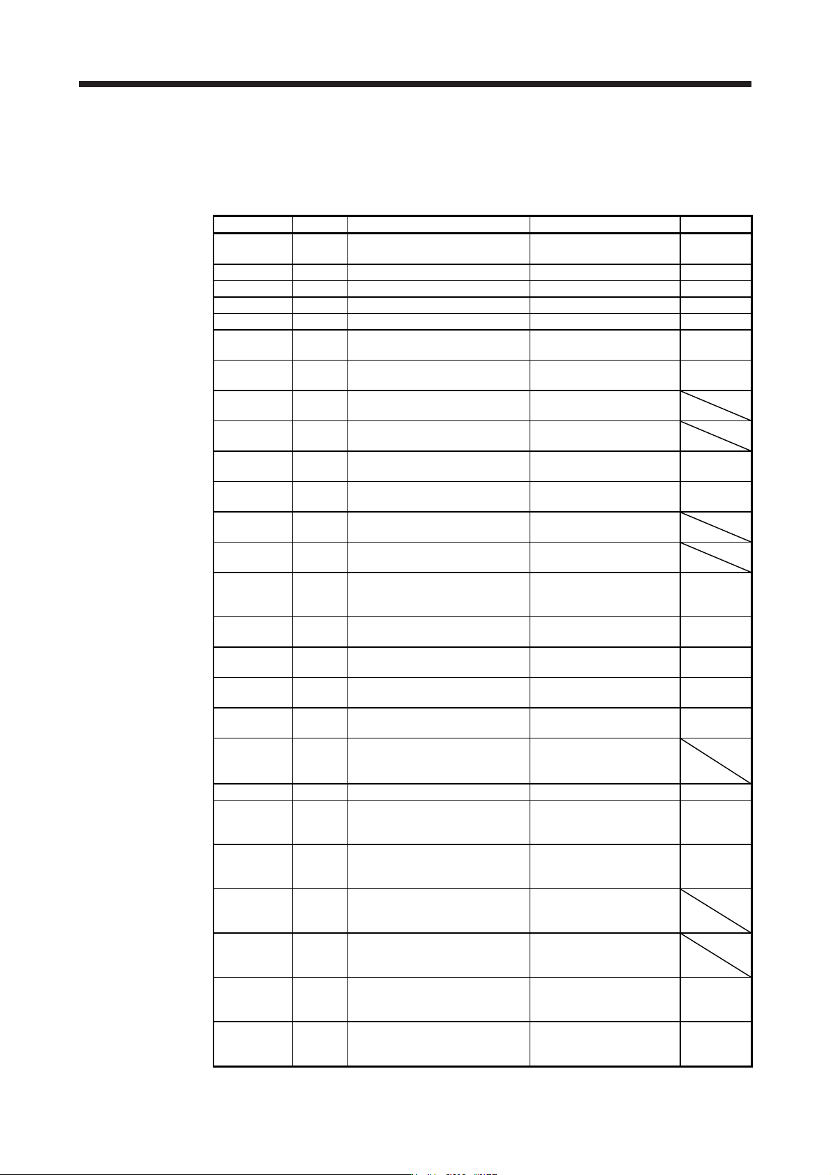
17. APPLICATIO N OF FUNCTIONS 17 - 54 Parameter S ymbol Nam e Setting v alue Unit PX10 VRF23B Vibration s uppression cont rol 2 - Vibration f requency damping after gain switc hing 0.05 PX11 VRF24B Vibration s uppression…
17. APPLICATION OF FUNCTIONS
17 - 53
(d) Gain switching procedure
This operation will be described by way of setting examples.
1) When you choose switching by control command from the controller
a) Setting example
Parameter Symbol Name Setting value Unit
PB06 GD2
Load to motor inertia ratio/load to
motor mass ratio
4.00 [Multiplier]
PB07 PG1 Model loop gain 100 [rad/s]
PB08 PG2 Position loop gain 120 [rad/s]
PB09 VG2 Speed loop gain 3000 [rad/s]
PB10 VIC Speed integral compensation 20 [ms]
PB19 VRF11
Vibration suppression control 1 -
Vibration frequency
50 [Hz]
PB20 VRF12
Vibration suppression control 1 -
Resonance frequency
50 [Hz]
PB21 VRF13
Vibration suppression control 1 -
Vibration frequency damping
0.20
PB22 VRF14
Vibration suppression control 1 -
Resonance frequency damping
0.20
PX04 VRF21
Vibration suppression control 2 -
Vibration frequency
20 [Hz]
PX05 VRF22
Vibration suppression control 2 -
Resonance frequency
20 [Hz]
PX06 VRF23
Vibration suppression control 2 -
Vibration frequency damping
0.10
PX07 VRF24
Vibration suppression control 2 -
Resonance frequency damping
0.10
PB29 GD2B
Load to motor inertia ratio/load to
motor mass ratio after gain
switching
10.00 [Multiplier]
PX12 PG1B
Model loop gain after gain
switching
50 [rad/s]
PB30 PG2B
Position loop gain after gain
switching
84 [rad/s]
PB31 VG2B
Speed loop gain after gain
switching
4000 [rad/s]
PB32 VICB
Speed integral compensation after
gain switching
50 [ms]
PB26 CDP Gain switching function 0001
(Switch by control command
from the controller.)
PB28 CDT Gain switching time constant 100 [ms]
PB33 VRF11B
Vibration suppression control 1 -
Vibration frequency after gain
switching
60 [Hz]
PB34 VRF12B
Vibration suppression control 1 -
Resonance frequency after gain
switching
60 [Hz]
PB35 VRF13B
Vibration suppression control 1 -
Vibration frequency damping after
gain switching
0.15
PB36 VRF14B
Vibration suppression control 1 -
Resonance frequency damping
after gain switching
0.15
PX08 VRF21B
Vibration suppression control 2 -
Vibration frequency after gain
switching
30 [Hz]
PX09 VRF22B
Vibration suppression control 2 -
Resonance frequency after gain
switching
30 [Hz]
17. APPLICATION OF FUNCTIONS
17 - 54
Parameter Symbol Name Setting value Unit
PX10 VRF23B
Vibration suppression control 2 -
Vibration frequency damping after
gain switching
0.05
PX11 VRF24B
Vibration suppression control 2 -
Resonance frequency damping
after gain switching
0.05
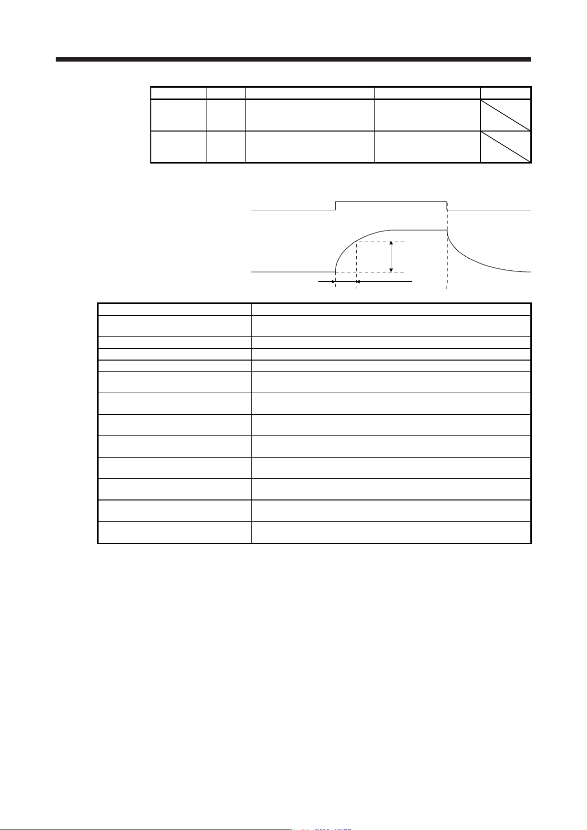
b) Switching timing chart
After-switching gain
63.4%
CDT = 100 ms
Before-switching gain
Gain switching
Control command
from controller
OFF
ON
OFF
Model loop gain 100 → 50 → 100
Load to motor inertia ratio/load to motor
mass ratio
4.00 → 10.00 → 4.00
Position loop gain 120 → 84 → 120
Speed loop gain 3000 → 4000 → 3000
Speed integral compensation 20 → 50 → 20
Vibration suppression control 1 - Vibration
frequency
50 → 60 → 50
Vibration suppression control 1 -
Resonance frequency
50 → 60 → 50
Vibration suppression control 1 - Vibration
frequency damping
0.20 → 0.15 → 0.20
Vibration suppression control 1 -
Resonance frequency damping
0.20 → 0.15 → 0.20
Vibration suppression control 2 - Vibration
frequency
20 → 30 → 20
Vibration suppression control 2 -
Resonance frequency
20 → 30 → 20
Vibration suppression control 2 - Vibration
frequency damping
0.10 → 0.05 → 0.10
Vibration suppression control 2 -
Resonance frequency damping
0.10 → 0.05 → 0.10
17. APPLICATION OF FUNCTIONS
17 - 55
2) When you choose switching by droop pulses
The vibration suppression control after gain switching and model loop gain after gain switching
cannot be used.
a) Setting example
Parameter Symbol Name Setting value Unit
PB06 GD2
Load to motor inertia ratio/load to
motor mass ratio
4.00 [Multiplier]
PB08 PG2 Position loop gain 120 [rad/s]
PB09 VG2 Speed loop gain 3000 [rad/s]
PB10 VIC Speed integral compensation 20 [ms]
PB29 GD2B
Load to motor inertia ratio/load to
motor mass ratio after gain
switching
10.00 [Multiplier]
PB30 PG2B
Position loop gain after gain
switching
84 [rad/s]
PB31 VG2B
Speed loop gain after gain
switching
4000 [rad/s]
PB32 VICB
Speed integral compensation after
gain switching
50 [ms]
PB26 CDP Gain switching selection 0003
(switching by droop pulses)
PB27 CDL Gain switching condition 50 [pulse]
PB28 CDT Gain switching time constant 100 [ms]
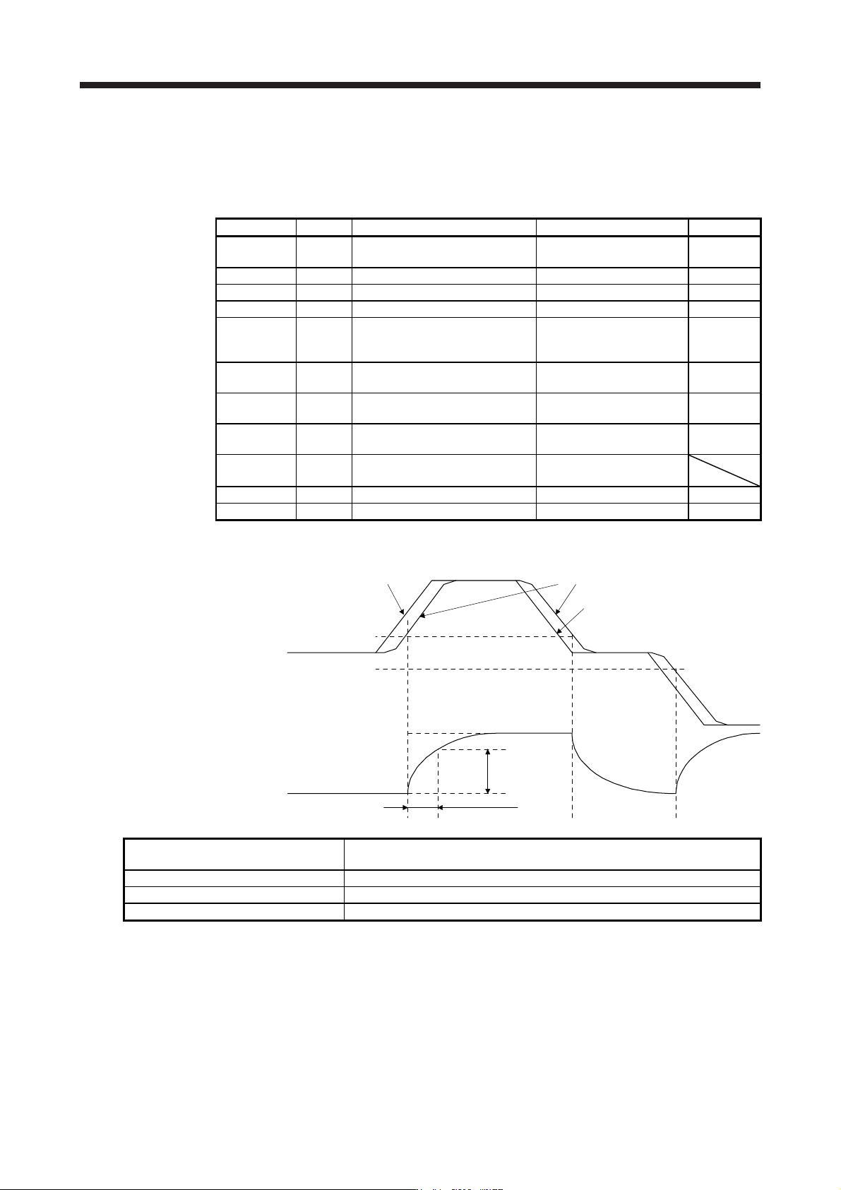
b) Switching timing chart
After-switching gain
63.4%
CDT = 100 ms
Before-switching gain
Gain switching
Droop pulses
[pulse]
+CDL
-CDL
0
Command pulses
Droop pulses
Command pulses
Load to motor inertia ratio/load to motor
mass ratio
4.00 → 10.00 → 4.00 → 10.00
Position loop gain 120 → 84 → 120 → 84
Speed loop gain 3000 → 4000 → 3000 → 4000
Speed integral compensation 20 → 50 → 20 → 50