sh030106u.pdf - 第357页
11. OPT ION S AND P ERI PHER AL EQU IPMENT 11 - 36 2) Contro l circuit term inal POINT Under tigh tening can caus e a cab le disc onnectio n or m alfunct ion . Over tightening can caus e a shor t cir cuit or malfunct ion…
11. OPTIONS AND PERIPHERAL EQUIPMENT
11 - 35
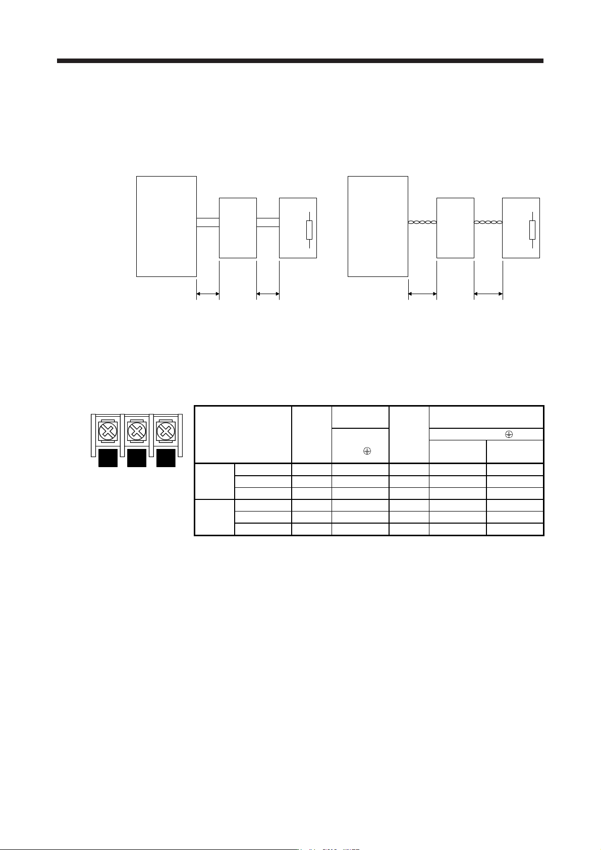
(3) Connection instructions
Keep the wires between the servo amplifier and the brake unit, and between the resistor unit and the
brake unit as short as possible. For wires longer than 5 m, twist the wires five times or more per meter.
The wires should not exceed 10 m even when the wires are twisted. If wires exceeding 5 m without
twisted or exceeding 10 m with or without twisted are used, the brake unit may malfunction.
Servo amplifier
Brake unit
5 m or less 5 m or less
Servo amplifier
Brake unit
10 m or less 10 m or less
P+
N-
P/+
N/-
P
PR
P
PR
P/+
N/-
P
PR
P
PR
Twist Twist
Resistor unit Resistor unit
P+
N-
(4) Wires
(a) Wires for the brake unit
For the brake unit, HIV wire (600 V Grade heat-resistant polyvinyl chloride insulated wire) is
recommended.
1) Main circuit terminal
N/- P/+ PR
Terminal block
Brake unit
Main
circuit
screw
size
Crimp
terminal
Tightening
torque
[N•m]
Wire size
N/-, P/+,
PR,
N/-, P/+, PR,
HIV wire
[mm
2
]
AWG
200 V
class
FR-BU2-15K M4 5.5-4 1.5 3.5 12
FR-BU2-30K M5 5.5-5 2.5 5.5 10
FR-BU2-55K M6 14-6 4.4 14 6
400 V
class
FR-BU2-H30K M4 5.5-4 1.5 3.5 12
FR-BU2-H55K M5 5.5-5 2.5 5.5 10
FR-BU2-H75K M6 14-6 4.4 14 6
11. OPTIONS AND PERIPHERAL EQUIPMENT
11 - 36
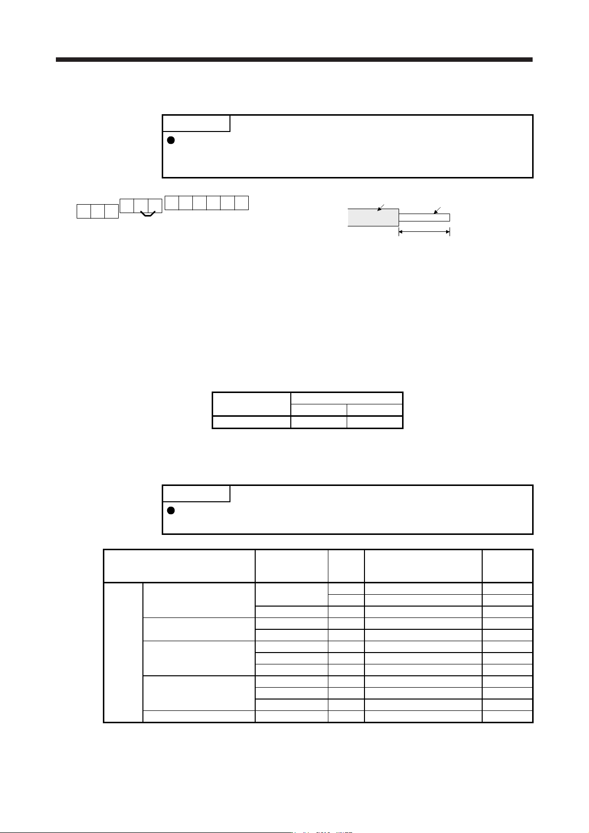
2) Control circuit terminal
POINT
Under tightening can cause a cable disconnection or malfunction. Over
tightening can cause a short circuit or malfunction due to damage to the screw
or the brake unit.
A
RES
PC
B
SD
BUE
C
MSG
SD
MSG
SD SD
Jumper
Terminal block
Insulator
Core
6 mm
Wire the stripped cable after twisting to prevent the cable
from becoming loose. In addition, do not solder it.
Screw size: M3
Tightening torque: 0.5 N•m to 0.6 N•m
Wire size: 0.3 mm
2
to 0.75 mm
2
Screw driver: Small flat-blade screwdriver
(Tip thickness: 0.4 mm/Tip width 2.5 mm)
(b) Cables for connecting the servo amplifier and a distribution terminal block when connecting two sets
of the brake unit
Brake unit
Wire size
HIV wire [mm
2
]AWG
FR-BU2-15K 8 8
(5) Crimp terminals for P+ and N- terminals of servo amplifier
(a) Recommended crimp terminals
POINT
Some crimp terminals may not be mounted depending on the size. Make sure to
use the recommended ones or equivalent ones.
Servo amplifier Brake unit
Number of
connected
units
Crimp terminal (Manufacturer)
(Note 1)
Applicable
tool
200 V
class
MR-J4-500B(-RJ) FR-BU2-15K 1 FVD5.5-S4 (JST) a
2 8-4NS (JST) (Note 2) b
FR-BU2-30K 1 FVD5.5-S4 (JST) a
MR-J4-700B(-RJ) FR-BU2-15K 2 8-4NS (JST) (Note 2) b
FR-BU2-30K 1 FVD5.5-S4 (JST) a
MR-J4-11KB(-RJ) FR-BU2-15K 2 FVD8-6 (JST) c
FR-BU2-30K 1 FVD5.5-6 (JST) a
FR-BU2-55K 1 FVD14-6 (JST) d
MR-J4-15KB(-RJ) FR-BU2-15K 2 FVD8-6 (JST) c
FR-BU2-30K 1 FVD5.5-6 (JST) a
FR-BU2-55K 1 FVD14-6 (JST) d
MR-J4-22KB(-RJ) FR-BU2-55K 1 FVD14-8 (JST) d
11. OPTIONS AND PERIPHERAL EQUIPMENT
11 - 37
Servo amplifier Brake unit
Number of
connected
units
Crimp terminal (Manufacturer)
(Note 1)
Applicable
tool
400 V
class
MR-J4-500B4(-RJ) FR-BU2-H30K 1 FVD5.5-S4 (JST) a
MR-J4-700B4(-RJ) FR-BU2-H30K 1 FVD5.5-S4 (JST) a
MR-J4-11KB4(-RJ) FR-BU2-H30K 1 FVD5.5-6 (JST) a
FR-BU2-H55K 1 FVD5.5-6 (JST) a
MR-J4-15KB4(-RJ) FR-BU2-H55K 1 FVD5.5-6 (JST) a
MR-J4-22KB4(-RJ) FR-BU2-H55K 1 FVD5.5-8 (JST) a
FR-BU2-H75K 1 FVD14-8 (JST) d
Note 1. S
y
mbols in the applicable tool field indicate applicable tools in
(
4
)
(
b
)
in this section.
2. Coat the crimpin
g
part with an insulation tube.
(b) Applicable tool
Symbol
Servo amplifier-side crimp terminals
Crimp terminal
Applicable tool
Manufacturer
Body Head Dice
a
FDV5.5-S4
FDV5.5-6
YNT-1210S
JST
b 8-4NS YHT-8S
c FVD8-6
YF-1
E-4
YNE-38 DH-111
DH-121
d
FVD14-6
FVD14-8
YF-1
E-4
YNE-38 DH-112
DH-122
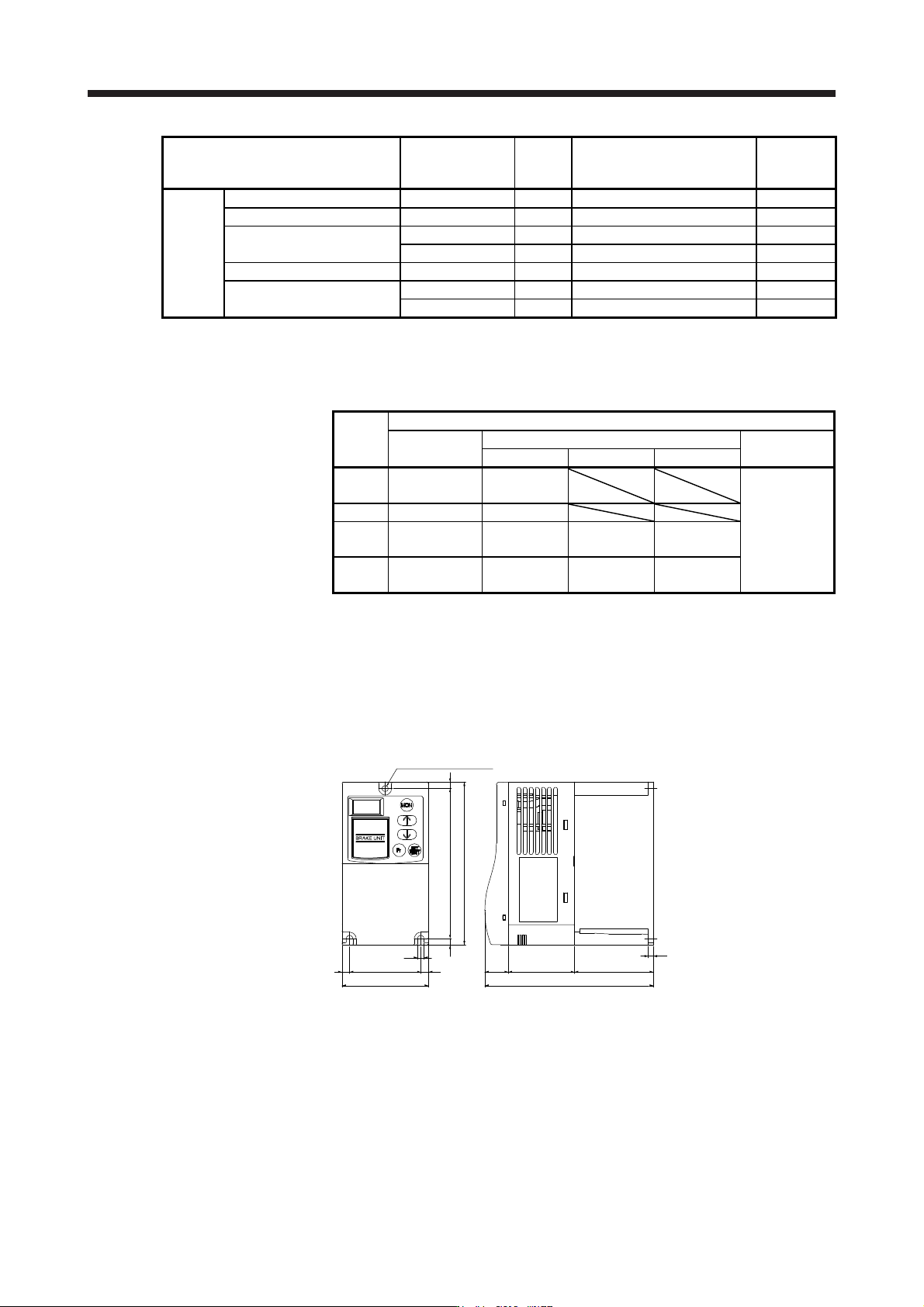
11.3.4 Dimensions
(1) FR-BU2-(H) brake unit
FR-BU2-15K
[Unit: mm]
Rating
plate
φ5 hole
(Screw size: M4)
68
6 56 6
5
5 118
5
128
18.5
52 62
4
132.5