sh030106u.pdf - 第35页
1. FUNCTI ONS AND CONF IGURATION 1 - 18 Model: MR-J4- _(-RJ) 10B 1 20B1 40B1 Environm ent Ambient temperat ure Operati on 0 °C to 55 °C ( non-f reezin g) Sto rage -20 °C to 65 °C (non -fre ezin g) Ambient humidity Oper a…
1. FUNCTIONS AND CONFIGURATION
1 - 17
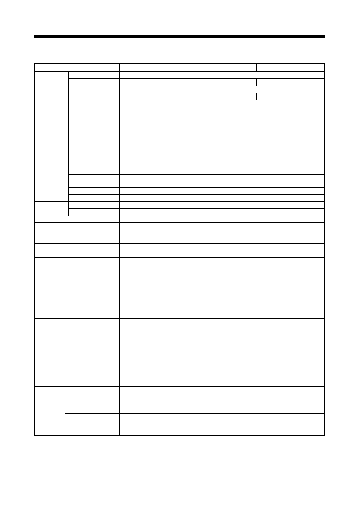
(3) 100 V class
Model: MR-J4-_(-RJ) 10B1 20B1 40B1
Output
Rated voltage 3-phase 170 V AC
Rated current [A] 1.1 1.5 2.8
Main circuit
power supply
input
Voltage/Frequency 1-phase 100 V AC to 120 V AC, 50 Hz/60 Hz
Rated current [A] 3.0 5.0 9.0
Permissible voltage
fluctuation
1-phase 85 V AC to 132 V AC
Permissible frequency
fluctuation
Within ±5%
Power supply capacity
[kVA]
Refer to section 10.2.
Inrush current [A] Refer to section 10.5.
Control circuit
power supply
input
Voltage/Frequency 1-phase 100 V AC to 120 V AC, 50 Hz/60 Hz
Rated current [A] 0.4
Permissible voltage
fluctuation
1-phase 85 V AC to 132 V AC
Permissible frequency
fluctuation
Within ±5%
Power consumption [W] 30
Inrush current [A] Refer to section 10.5.
Interface power
supply
Voltage 24 V DC ± 10%
Current capacity [A] 0.3 (including CN8 connector signals) (Note 1)
Control method Sine-wave PWM control, current control method
Dynamic brake Built-in
SSCNET III/H communication cycle
(Note 6)
0.222 ms, 0.444 ms, 0.888 ms
Fully closed loop control Compatible (Note 5)
Scale measurement function Compatible (Note 7)
Load-side encoder interface (Note 4) Mitsubishi Electric high-speed serial communication
Communication function USB: connection to a personal computer or others (MR Configurator2-compatible)
Encoder output pulses Compatible (A/B/Z-phase pulse)
Analog monitor Two channels
Protective functions
Overcurrent shut-off, regenerative overvoltage shut-off, overload shut-off (electronic thermal), servo motor
overheat protection, encoder error protection, regenerative error protection, undervoltage protection,
instantaneous power failure protection, overspeed protection, error excessive protection, magnetic pole
detection protection, and linear servo control fault protection
Functional safety STO (IEC/EN 61800-5-2)
Safety
performance
Standards (Note 8)
EN ISO 13849-1:2015 Category 3 PL e, IEC 61508 SIL 3,
EN IEC 62061 maximum SIL 3, EN 61800-5-2
Response performance 8 ms or less (STO input off → energy shut off)
Test pulse input (STO)
(Note 3)
Test pulse interval: 1 Hz to 25 Hz
Test pulse off time: Up to 1 ms
Mean time to dangerous
failure (MTTFd)
MTTFd ≥ 100 [years] (314a)
Diagnostic coverage (DC) DC = Medium, 97.6 [%]
Probability of dangerous
failures per hour (PFH)
PFH = 6.4 × 10
-9
[1/h]
Global
standards
CE marking
LVD: EN 61800-5-1, EMC: EN 61800-3, MD: EN ISO 13849-1:2015, EN 61800-5-2,
EN IEC 62061
UKCA marking
LVD: BS EN 61800-5-1, EMC: BS EN IEC 61800-3, MD: BS EN ISO 13849-1:2015, BS EN 61800-5-2,
BS EN IEC 62061
UL standard UL 61800-5-1
Structure (IP rating) Natural cooling, open (IP20)
Close mounting (Note 2) Possible

1. FUNCTIONS AND CONFIGURATION
1 - 18
Model: MR-J4-_(-RJ) 10B1 20B1 40B1
Environment
Ambient
temperature
Operation 0 °C to 55 °C (non-freezing)
Storage -20 °C to 65 °C (non-freezing)
Ambient
humidity
Operation
5 %RH to 90 %RH (non-condensing)
Storage
Ambience
Indoors (no direct sunlight),
free from corrosive gas, flammable gas, oil mist, dust, and dirt
Altitude 2000 m or less above sea level (Note 9)
Vibration resistance 5.9 m/s
2
, at 10 Hz to 55 Hz (directions of X, Y and Z axes)
Mass [kg] 0.8 1.0
Note 1. 0.3 A is the value applicable when all I/O signals are used. The current capacity can be decreased by reducing the number of
I/O points.
2. When closely mounting the servo amplifiers, operate them at the ambient temperature of 0 °C to 45 °C or at 75% or smaller
effective load ratio.
3. Test pulse is a signal which instantaneously turns off a signal to the servo amplifier at a constant period for external circuit to
self-dia
g
nose.
4. MR-J4-_B servo amplifier is compatible only with two-wire type. MR-J4-_B-RJ servo amplifier is compatible with two-wire type,
fou
r
-wire t
y
pe, and A/B/Z-phase differential output method. Refer to
t
able 1.1 for details.
5. For the compatible version of full
y
closed loop s
y
stem, refer to table 1.1.
6 The communication c
y
cle depends on the controller specifications and the number of axes connected.
7. For the compatible version for the scale measurement function, refer to table 1.1.
8. The safety level depends on the setting value of [Pr. PF18 STO diagnosis error detection time] and whether STO input
dia
g
nosis b
y
TOFB output is performed or not. For details, refer to the Function column of [Pr. PF18] in section 5.2.6.
9. Follow the restrictions in section 2.7 when usin
g
this product at altitude exceedin
g
1000 m and up to 2000 m above sea level.
1. FUNCTIONS AND CONFIGURATION
1 - 19
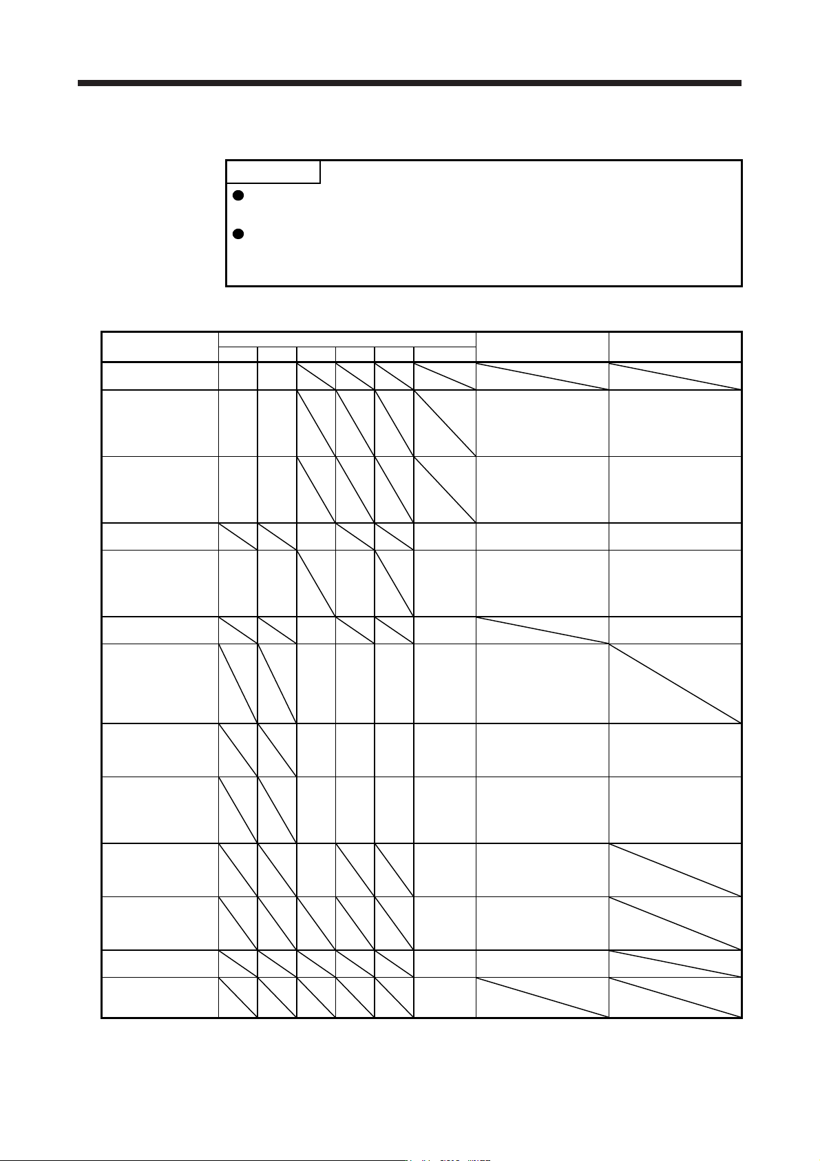
1.4 Combinations of servo amplifiers and servo motors
POINT
When a 1-phase 200 V AC input is used, the maximum torque of 400% cannot
be achieved with HG-JR series servo motor.
When you use the MR-J4-100B(-RJ) or MR-J4-200B(-RJ) with the 1-phase 200
V AC input, contact your local sales office for the torque characteristics of the
HG-UR series, HG-RR series, and HG-JR series servo motors.
(1) 200 V class
Servo amplifier
Rotary servo motor
Linear servo motor
(primary side)
Direct drive motor
HG-KR HG-MR HG-SR HG-UR HG-RR HG-JR
MR-J4-10B(-RJ) 053
13
053
13
MR-J4-20B(-RJ)
23 23
LM-U2PAB-05M-0SS0
LM-U2PBB-07M-1SS0
TM-RFM002C20
TM-RG2M002C30 (Note 1)
TM-RU2M002C30 (Note 1)
TM-RG2M004E30 (Note 1)
TM-RU2M004E30 (Note 1)
MR-J4-40B(-RJ)
43 43
LM-H3P2A-07P-BSS0
LM-H3P3A-12P-CSS0
LM-K2P1A-01M-2SS1
LM-U2PAD-10M-0SS0
LM-U2PAF-15M-0SS0
TM-RFM004C20
TM-RG2M004E30 (Note 1, 3)
TM-RU2M004E30 (Note 1, 3)
TM-RG2M009G30 (Note 1)
TM-RU2M009G30 (Note 1)
MR-J4-60B(-RJ)
51
52
53
LM-U2PBD-15M-1SS0 TM-RFM006C20
TM-RFM006E20
MR-J4-70B(-RJ)
73 73 72 73
LM-H3P3B-24P-CSS0
LM-H3P3C-36P-CSS0
LM-H3P7A-24P-ASS0
LM-K2P2A-02M-1SS1
LM-U2PBF-22M-1SS0
TM-RFM012E20
TM-RFM012G20
TM-RFM040J10
MR-J4-100B(-RJ)
81
102
53 (Note 2)
103
TM-RFM018E20
MR-J4-200B(-RJ)
121
201
152
202
152
103
153
73 (Note 2)
103 (Note 2)
153
203
LM-H3P3D-48P-CSS0
LM-H3P7B-48P-ASS0
LM-H3P7C-72P-ASS0
LM-FP2B-06M-1SS0
LM-K2P1C-03M-2SS1
LM-U2P2B-40M-2SS0
MR-J4-350B(-RJ)
301
352
202 203
153 (Note 2)
203 (Note 2)
353
LM-H3P7D-96P-ASS0
LM-K2P2C-07M-1SS1
LM-K2P3C-14M-1SS1
LM-U2P2C-60M-2SS0
TM-RFM048G20
TM-RFM072G20
TM-RFM120J10
MR-J4-500B(-RJ)
421
502
352
502
353
503
353 (Note 2)
503
LM-FP2D-12M-1SS0
LM-FP4B-12M-1SS0
LM-K2P2E-12M-1SS1
LM-K2P3E-24M-1SS1
LM-U2P2D-80M-2SS0
TM-RFM240J10
MR-J4-700B(-RJ)
702
503 (Note 2)
601
701M
703
LM-FP2F-18M-1SS0
LM-FP4D-24M-1SS0
MR-J4-11KB(-RJ)
801
12K1
11K1M
903
LM-FP4F-36M-1SS0
MR-J4-15KB(-RJ)
15K1
15K1M
LM-FP4F-48M-1SS0
MR-J4-22KB(-RJ)
20K1
25K1
22K1M
Note 1. This is available with servo amplifiers with software version C8 or later.
2. This combination increases the maximum torque of the servo motor to 400%.
3. This combination increases the rated torque and the maximum torque.