sh030106u.pdf - 第494页
14. USIN G A LINEAR SER VO MOTOR 14 - 27 (b) Sett ings of the numb er of p ulses (AP) an d travel dis tanc e ( AL) AP AL Position feedback [mm] Command [mm] + - Speed feedback [mm/s] AL AP User Controlle r Servo amplifie…

14. USING A LINEAR SERVO MOTOR
14 - 26
(1) Operation method
For the system using the incremental linear encoder, the magnetic pole detection is automatically
performed at the first servo-on after the power-on. For this reason, when performing the positioning
operation, create the sequence which surely confirms the servo-on status as the inter lock condition of
the positioning command.
Also, some parameter settings and the home position return type differ according to the controller type.
(2) Servo system controller setting
(a) Setting precautions
The following parameters will be enabled by cycling the servo amplifier power after the controller
writes the parameters to the servo amplifier.
Setting item
Set content
Motion controller
R_MTCPU/Q17_DSCPU
Simple motion module
RD77MS_/QD77MS_ /
LD77MS_
Command resolution Linear encoder resolution unit
Parameter
Servo amplifier setting MR-J4-B Linear
Motor setting Automatic setting
No.
(Note)
Symbol
Name
Initial
value
PA01 **STY Operation mode 1000h 1040h
PC01 ERZ Error excessive alarm level 0
Set the items as required.
PC03 *ENRS Encoder output pulse selection 0000h
PC27 **COP9 Function selection C-9 0000h
PL01 **LIT1
Linear servo motor/DD motor function
selection 1
0301h
PL02 **LIM Linear encoder resolution - Numerator 1000
PL03 **LID
Linear encoder resolution -
Denominator
1000
PL04 *LIT2
Linear servo motor/DD motor function
selection 2
0003h
PL05 LB1 Position deviation error detection level 0
PL06 LB2 Speed deviation error detection level 0
PL07 LB3
Torque/thrust deviation error detection
level
100
PL08 *LIT3
Linear servo motor/DD motor function
selection 3
0010h
PL09 LPWM Magnetic pole detection voltage level 30
PL17 LTSTS
Magnetic pole detection - Minute
position detection method - Function
selection
0000h
PL18 IDLV
Magnetic pole detection - Minute
position detection method -
Identification signal amplitude
0
Positioning
control
parameter
Unit setting mm
Number of pulses (AP)
Travel distance (AL)
Refer to (2) (b) in this section.
Note. The parameter whose symbol is preceded by * is enabled with the following conditions.
* : After setting the parameter, power off and on the servo amplifier or reset the controller.
**: After settin
g
the parameter, c
y
cle the power of the servo amplifier.
14. USING A LINEAR SERVO MOTOR
14 - 27
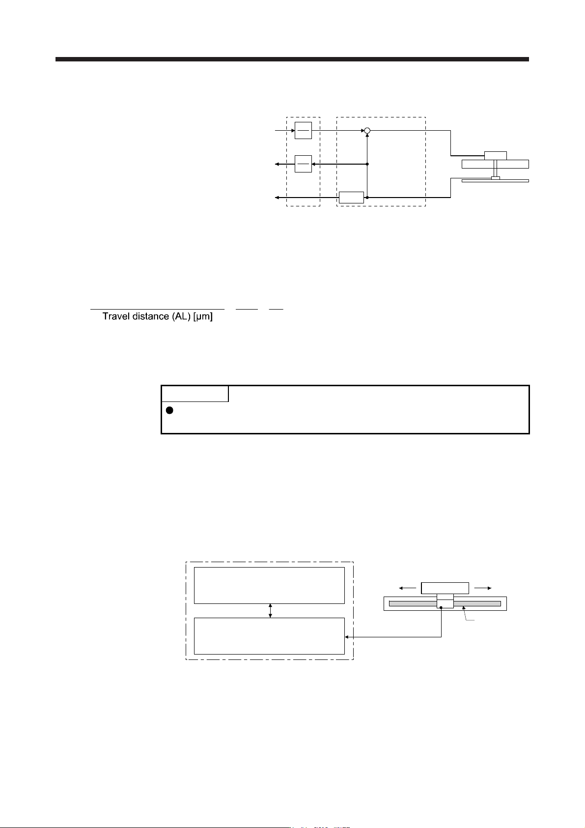
(b) Settings of the number of pulses (AP) and travel distance (AL)
AP
AL
Position feedback
[mm]
Command
[mm]
+
-
Speed feedback
[mm/s]
AL
AP
User
Controlle
r
Servo amplifier
Linear servo
motor
Linear encoder
Differ-
entiation
Calculate the number of pulses (AP) and travel distance (AL) of the linear encoder in the following
conditions.
When the linear encoder resolution is 0.05 µm
Number of pulses (AP) [pulse]
=
1
0.05
=
20
1
14.3.6 Function
(1) Linear servo control error detection function
POINT
For the linear servo control error detection function, the position and speed
deviation error detections are enabled by default. ([Pr. PL04]: _ _ _ 3)
If the linear servo control gets unstable for some reasons, the linear servo motor may not operate
properly. To detect this state and to stop operation, the linear servo control error detection function is
used as a protective function.
The linear servo control error detection function has three different detection methods: the position
deviation, speed deviation, and thrust deviation. An error is detected when each method is enabled with
[Pr. PL04 Linear servo motor/DD motor function selection 2]. The detection level can be changed with
[Pr. PL05], [Pr. PL06], and [Pr. PL07].
Servo amplifier internal value
1) Model feedback position [mm]
3) Model feedback speed [mm/s]
5) Command thrust [%]
Linear encoder
2) Feedback position [mm]
4) Feedback speed [mm/s]
6) Feedback thrust [%]
Servo amplifier
Linear servo motor
Linear encoder
Figure 14.1 Outline of linear servo control error detection function

14. USING A LINEAR SERVO MOTOR
14 - 28
(a) Position deviation error detection
Set [Pr. PL04] to "_ _ _ 1" to enable the position deviation error detection.
[Pr. PL04]
Position deviation error detection enabled
1
When you compare the model feedback position ( 1)) and the feedback position ( 2)) in figure 14.1, if
the deviation is more than the value of [Pr. PL05 Position deviation error detection level] (1 mm to
1000 mm), [AL. 42.1 Servo control error by position deviation] will occur and the linear servo motor
will stop. The initial value of this detection level is 50 mm. Replace the set value as required.
(b) Speed deviation error detection
Set [Pr. PL04] to "_ _ _ 2" to enable the speed deviation error detection.
[Pr. PL04]
Speed deviation error detection enable
d
2
When you compare the model feedback speed ( 3)) and the feedback speed ( 4)) in figure 14.1, if the
deviation is more than the value of [Pr. PL06 Speed deviation error detection level] (1 mm/s to 5000
mm/s), [AL. 42.2 Servo control error by speed deviation] will occur and the linear servo motor will
stop. The initial value of this detection level is 1000 mm/s. Replace the set value as required.
(c) Thrust deviation error detection level
Set [Pr. PL04] to "_ _ _ 4" to enable the thrust deviation error detection.
[Pr. PL04]
Thrust deviation error detection enabled
4
When you compare the command thrust ( 5)) and the feedback thrust ( 6)) in figure 14.1, if the
deviation is more than the value of [Pr. PL07 Torque/thrust deviation error detection level] (1% to
1000%), [AL. 42.3 Servo control error by torque/thrust deviation] will occur and the linear servo motor
will stop. The initial value of this detection level is 100%. Replace the set value as required.
(d) Detecting multiple deviation errors
When setting [Pr. PL04] as shown below, multiple deviation errors can be detected. For the error
detection methods, refer to (1) (a), (b), (c) in this section.
[Pr. PL04]
Position deviation
error detection
Setting
value
Speed deviation
error detection
Thrust deviation
error detection
1
5
6
7
3
2
4