sh030106u.pdf - 第330页
11. OPT ION S AND P ERI PHER AL EQU IPMENT 11 - 9 11.1.4 Batter y cab le/junc tion bat tery cabl e (1) Model exp lanat ions The numb ers in t he cable lengt h field of the tab le indic ate the s ymbol f illing t he un de…
11. OPTIONS AND PERIPHERAL EQUIPMENT
11 - 8
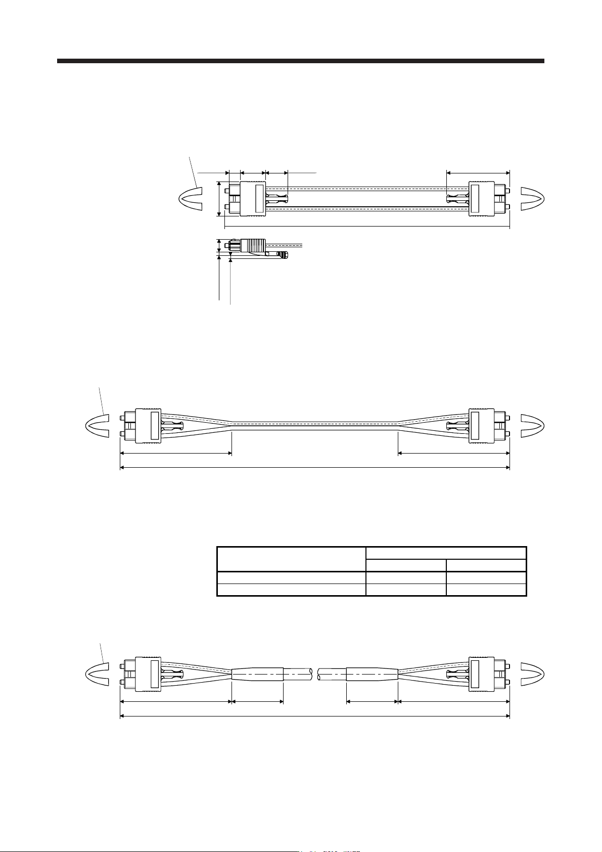
(3) Dimensions
(a) MR-J3BUS015M
[Unit: mm]
150
Approx.
6.7
8
+0
+50
- 0
Protective tube
Approx.
15
Approx.
13.4
Approx.
20.9
Approx. 2.3
Approx. 1.7
Approx.
37.65
(b) MR-J3BUS03M to MR-J3BUS3M
Refer to the table shown in (1) in this section for cable length (L).
[Unit: mm]
L
(Note)
Protective tube
Approx. 100
Approx. 100
Note. Dimension of connector part is the same as that of MR-J3BUS015M.
(c) MR-J3BUS5M-A to MR-J3BUS20M-A/MR-J3BUS30M-B to MR-J3BUS50M-B
Refer to the table shown in (1) in this section for cable length (L).
SSCNET III cable
Variable dimensions [mm]
A B
MR-J3BUS5M-A to MR-J3BUS20M-A 100 30
MR-J3BUS30M-B to MR-J3BUS50M-B 150 50
[Unit: mm]
L
Protective tube
(Note)
Approx. A Approx. B Approx. B Approx. A
Note. Dimension of connector part is the same as that of MR-J3BUS015M.
11. OPTIONS AND PERIPHERAL EQUIPMENT
11 - 9
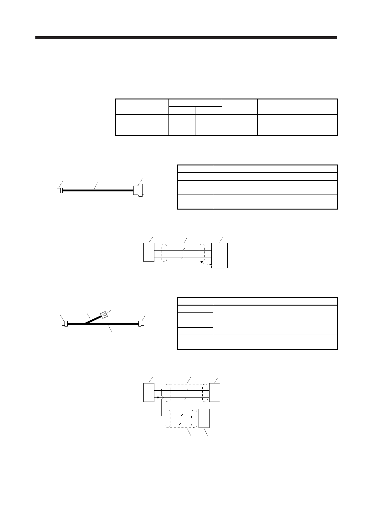
11.1.4 Battery cable/junction battery cable
(1) Model explanations
The numbers in the cable length field of the table indicate the symbol filling the underline "_" in the cable
model. The cables of the lengths with the symbols are available.
Cable model
Cable length
Bending life Application/remark
0.3 m 1 m
MR-BT6V1CBL_M 03 1 Standard
For connection with MR-
BT6VCASE
MR-BT6V2CBL_M 03 1 Standard For junction
(2) MR-BT6V1CBL_M
(a) Appearance
2) 1)
3)
Components Description
1) Cable VSVC 7/0.18 × 2C
2) Connector
Housing: PAP-02V-O
Contact: SPHD-001G-P0.5 (JST)
3) Connector
Connector: 10114-3000PE
Shell kit: 10314-52F0-008 (3M or equivalent)
(b) Internal wiring diagram
BT
LG
7
14
1
2
LG
BT
1)2) 3)
SD
White
Black
Plate
(3) MR-BT6V2CBL_M
(a) Appearance
1)
2)
3)4)
5)
Components Description
1) Cable
VSVC 7/0.18 × 2C
2) Cable
3) Connector
Housing: PAP-02V-O
Contact: SPHD-001G-P0.5 (JST)
4) Connector
5) Connector
Housing: PALR-02VF-O
Contact: SPAL-001GU-P0.5 (JST)
(b) Internal wiring diagram
BT
LG
1
2
1
2 LG
BT
3)
1
2LG
BT
White
Black
1)
4)
2) 5)
White
Black
11. OPTIONS AND PERIPHERAL EQUIPMENT
11 - 10
11.2 Regenerative options
CAUTION
Do not use servo amplifiers with regenerative options other than the combinations
specified below.
Otherwise, it may cause a fire.
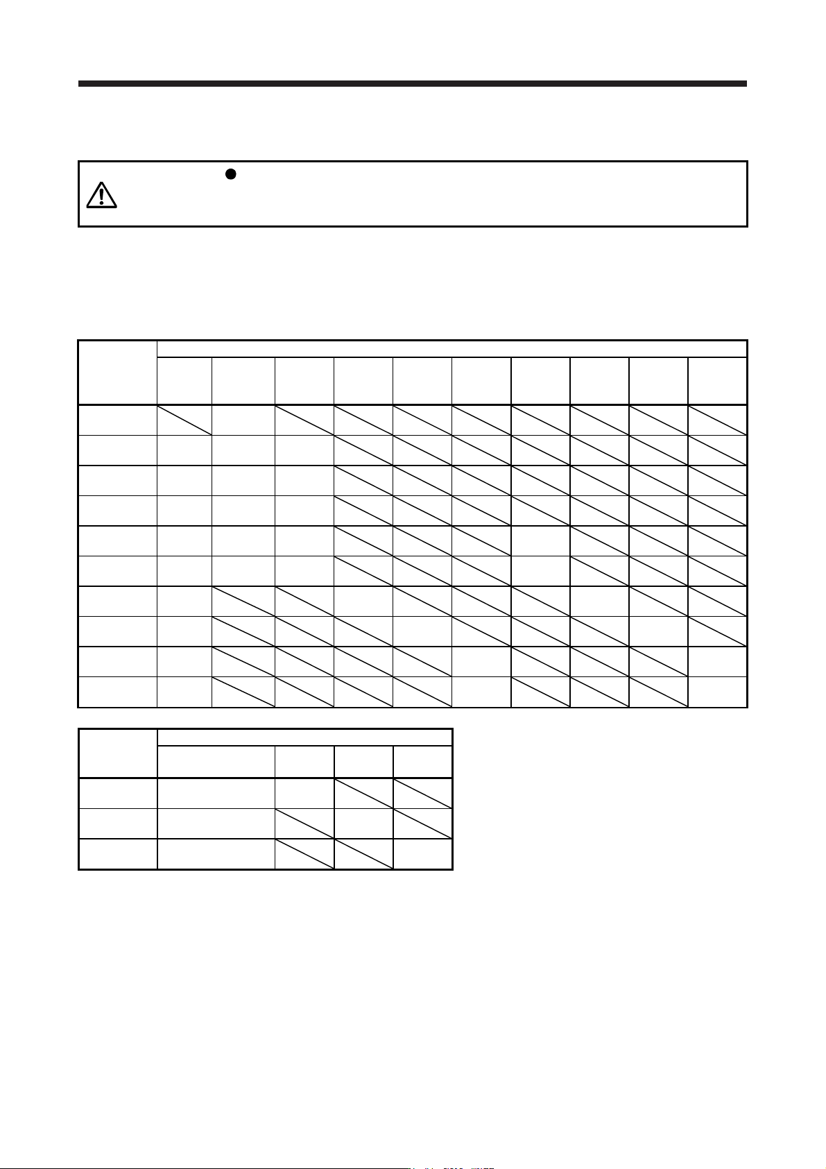
11.2.1 Combination and regenerative power
The power values in the table are resistor-generated powers and not rated powers.
(1) 200 V class
Servo
amplifier
Regenerative power [W]
Built-in
regenerative
resistor
MR-RB032
[40 Ω]
MR-RB12
[40 Ω]
MR-RB30
[13 Ω]
MR-RB3N
[9 Ω]
MR-RB31
[6.7 Ω]
MR-RB32
[40 Ω]
(Note 1)
MR-RB50
[13 Ω]
(Note 1)
MR-RB5N
[9 Ω]
(Note 1)
MR-RB51
[6.7 Ω]
MR-J4-10B
(-RJ)
30
MR-J4-20B
(-RJ)
10 30 100
MR-J4-40B
(-RJ)
10 30 100
MR-J4-60B
(-RJ)
10 30 100
MR-J4-70B
(-RJ)
20 30 100 300
MR-J4-100B
(-RJ)
20 30 100 300
MR-J4-200B
(-RJ)
100 300 500
MR-J4-350B
(-RJ)
100 300 500
MR-J4-500B
(-RJ)
130 300 500
MR-J4-700B
(-RJ)
170 300 500
Servo
amplifier
(Note 2) Regenerative power [W]
External regenerative
resistor (accessory)
MR-RB5R
[3.2 Ω]
MR-RB9F
[3 Ω]
MR-RB9T
[2.5 Ω]
MR-J4-11KB
(-RJ)
500 (800)
500
(800)
MR-J4-15KB
(-RJ)
850 (1300)
850
(1300)
MR-J4-22KB
(-RJ)
850 (1300)
850
(1300)
Note 1.
A
lwa
y
s install a coolin
g
fan.
2. Values in parentheses assume the installation of a coolin
g
fan.