sh030106u.pdf - 第659页
APPENDIX App. - 28 App. 10. 2 Sett ing POINT When you use a linear ser vo mot or, rep lace t he follow ing words in t he left to the words in the righ t. (serv o motor) spee d →( linear serv o motor) speed CCW direc tion…
APPENDIX
App. - 27
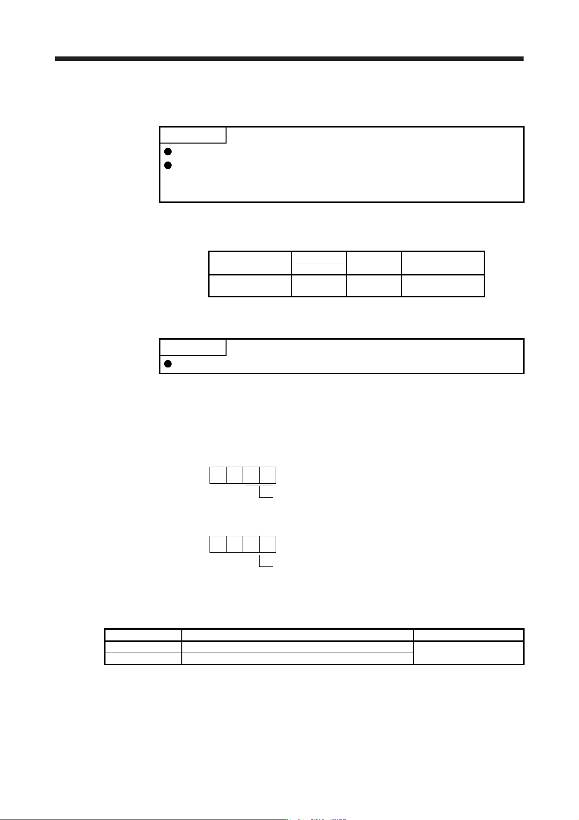
App. 9 SSCNET III cable (SC-J3BUS_M-C) manufactured by Mitsubishi Electric System &
Service
POINT
For the details of the SSCNET III cables, contact your local sales office.
Do not look directly at the light generated from CN1A/CN1B connector of servo
amplifier or the end of SSCNET III cable. The light can be a discomfort when it
enters the eye.
The cable is available per 1 m up to 100 m. The number of the length (1 to 100) will be in the underscore in
the cable model.
Cable model
Cable length
Bending life Application/remark
1 m to 100 m
SC-J3BUS_M-C 1 to 100
Ultra-long
bending life
Using long distance
cable
App. 10 Analog monitor
POINT
A voltage of analog monitor output may be irregular at power-on.
The servo status can be output to two channels in terms of voltage.
App. 10.1 Setting
Change the following digits of [Pr. PC09] and [Pr. PC10].
Analog monitor 1 output selection
(the signal provided to the output across MO1 and LG
)
00
[Pr. PC09]
Analog monitor 2 output selection
(the signal provided to the output across MO2 and LG
)
00
[Pr. PC10]
[Pr. PC11] and [Pr. PC12] can be used to set the offset voltages to the analog output voltages. Setting value
is -999 mV to 999 mV.
Parameter Description Setting range [mV]
PC11 This is used to set the offset voltage of MO1 (Analog monitor 1).
-999 to 999
PC12 This is used to set the offset voltage of MO2 (Analog monitor 2).
APPENDIX
App. - 28
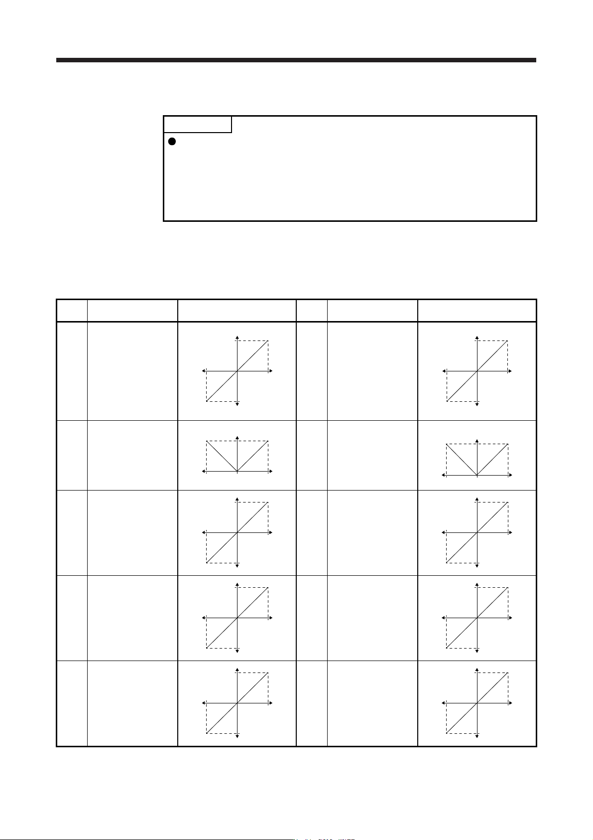
App. 10.2 Setting
POINT
When you use a linear servo motor, replace the following words in the left to the
words in the right.
(servo motor) speed →(linear servo motor) speed
CCW direction →Positive direction
CW direction →Negative direction
Torque →Thrust
The servo amplifier is factory-set to output the servo motor speed to MO1 (Analog monitor 1) and the
torque to MO2 (Analog monitor 2). The setting can be changed as listed below by setting the [Pr. PC09]
and [Pr. PC10] value.
Refer to (3) for the detection point.
Setting
value
Output item Description
Setting
value
Output item Description
00 Servo motor speed/
Linear servo motor
speed
Maximum speed
CW direction
CCW direction
Maximum speed
0
8 [V]
-8 [V]
01 Torque/Thrust (Note 8)
Maximum torqu
e
Power running i
n
CW direction
Power running i
n
CCW direction
Maximum torque
0
8 [V]
-8 [V]
02 Servo motor speed/
Linear servo motor
speed
Maximum speed
CW direction CCW direction
Maximum speed 0
8 [V]
03 Torque/Thrust (Note 8)
Maximum torqu
e
Power running i
n
CW direction
Power running i
n
CCW direction
Maximum torque 0
8 [V]
04
Current command
(Note 8)
Maximum current command
(Maximum torque command)
CW directio
n
CCW directio
n
Maximum current comman
d
(
Maximum torque comman
d
0
8 [V]
-8 [V]
05 Speed command
Maximum speed
CW directio
n
CCW directio
n
Maximum speed
0
8 [V]
-8 [V]
06
Servo motor-side droop
pulses
(Note 1, 3, 5, 6)
(±10 V/100 pulses)
100 [pulse]
CW directio
n
CCW directio
n
100 [pulse
]
0
10 [V]
-10 [V]
07
Servo motor-side droop
pulses
(Note 1, 3, 5, 6)
(±10 V/1000 pulses)
1000 [pulse]
CW directio
n
CCW directio
n
1000 [pulse
]
0
10 [V]
-10 [V]
08
Servo motor-side droop
pulses
(Note 1, 3, 5, 6)
(±10 V/10000 pulses)
10000 [pulse]
CW directio
n
CCW directio
n
10000 [pulse
]
0
10 [V]
-10 [V]
09
Servo motor-side droop
pulses
(Note 1, 3, 5, 6)
(±10 V/100000 pulses)
100000 [pulse]
CW directio
n
CCW directio
n
100000 [pulse
]
0
10 [V]
-10 [V]
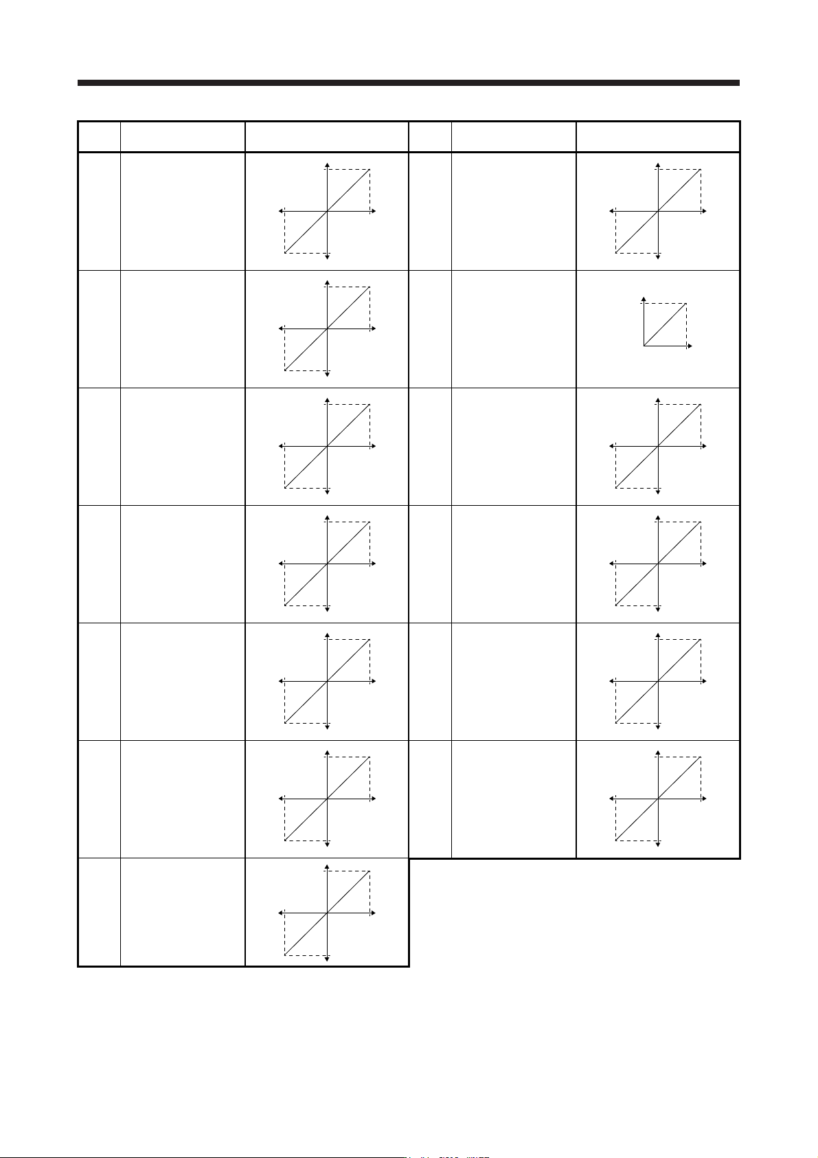
APPENDIX
App. - 29
Setting
value
Output item Description
Setting
value
Output item Description
0A
Feedback position
(Note 1, 2, 3)
(±10 V/1 Mpulse)
1 [Mpulse]
CW direction
CCW direction
1 [Mpulse
]
0
10 [V]
-10 [V]
0B
Feedback position
(Note 1, 2, 3)
(±10 V/10 Mpulse)
10 [Mpulse]
CW direction
CCW direction
10 [Mpulse
]
0
10 [V]
-10 [V]
0C
Feedback position
(Note 1, 2, 3)
(±10 V/100 Mpulse)
100 [Mpulse]
CW direction
CCW direction
100 [Mpulse
]
0
10 [V]
-10 [V]
0D Bus voltage (Note 7)
400 [V]
0
8 [V]
0E
Speed command 2
(Note 3)
Maximum speed
CW direction
CCW direction
Maximum speed
0
8 [V]
-8 [V]
10
Load-side droop pulses
(Note 3, 4, 5, 6)
(±10 V/100 pulses)
100 [pulse]
CW direction
CCW direction
100 [pulse
]
0
10 [V]
-10 [V]
11
Load-side droop pulses
(Note 3, 4, 5, 6)
(±10 V/1000 pulses)
1000 [pulse]
CW direction
CCW direction
1000 [pulse
]
0
10 [V]
-10 [V]
12
Load-side droop pulses
(Note 3, 4, 5, 6)
(±10 V/10000 pulses)
10000 [pulse]
CW direction
CCW direction
10000 [pulse
]
0
10 [V]
-10 [V]
13
Load-side droop pulses
(Note 3, 4, 5, 6)
(±10 V/100000 pulses)
100000 [pulse]
CW direction
CCW direction
100000 [pulse
]
0
10 [V]
-10 [V]
14
Load-side droop pulses
(Note 3, 4, 5, 6)
(±10 V/1 Mpulse)
1 [Mpulse]
CW direction
CCW direction
1 [Mpulse
]
0
10 [V]
-10 [V]
15
Motor-side/load-side
position deviation
(Note 3, 4, 5, 6)
(±10 V/100000 pulses)
100000 [pulse]
CW direction
CCW direction
100000 [pulse
]
0
10 [V]
-10 [V]
16
Servo motor-side/load-
side speed deviation
(Note 4)
Maximum speed
CW direction
CCW direction
Maximum speed
0
8 [V]
-8 [V]
17
Internal temperature of
encoder
(±10 V/±128 °C)
128 [°C]
-
128 [°C]
0
10 [V]
-10 [V]