sh030106u.pdf - 第262页
7. SPEC IAL ADJUSTMEN T FUNCT IONS 7 - 33 7.5 Model a daptiv e contr ol disabled POINT Change the p aram eters wh ile the s ervo mot or stops . When sett ing aut o tuning re sponse ( [Pr. P A09]), c hang e the sett i ng …

7. SPECIAL ADJUSTMENT FUNCTIONS
7 - 32
Instantaneous maximum output means power which servo amplifier can output in maximum torque at
rated speed. You can examine margins to compare the values of following conditions and instantaneous
maximum output.
Even if driving at maximum torque with low speed in actual operation, the motor will not drive with the
maximum output. This can be handled as a margin.
The following shows the conditions of tolerance against instantaneous power failure.
(a) Delta connection
For the 3-phase (L1/L2/L3) delta connection, an instantaneous power failure occurs in the voltage
between a pair of lines (e.g. between L1 and L2) among voltages between three pairs of lines
(between L1 and L2, L2 and L3, or L3 and L1).
(b) Star connection
For the 3-phase (L1/L2/L3/neutral point N) star connection, an instantaneous power failure occurs in
the voltage between a pair of lines (e.g. between L1 and N) among voltages at six locations,
between three pairs of lines (between L1 and L2, L2 and L3, or L3 and L1) and between one of the
lines and the neutral point (between L1 and N, L2 and N, or L3 and N).

7. SPECIAL ADJUSTMENT FUNCTIONS
7 - 33
7.5 Model adaptive control disabled
POINT
Change the parameters while the servo motor stops.
When setting auto tuning response ([Pr. PA09]), change the setting value one by
one to adjust it while checking operation status of the servo motor.
This is used with servo amplifiers with software version B4 or later.
(1) Summary
The servo amplifier has a model adaptive control. The servo amplifier has a virtual motor model and
drives the servo motor following the output of the motor model in the model adaptive control. At model
adaptive control disabled, the servo amplifier drives the motor with PID control without using the model
adaptive control.
The following shows the available parameters at model adaptive control disabled.
Parameter Symbol Name
PB08 PG2 Position loop gain
PB09 VG2 Speed loop gain
PB10 VIC Speed integral compensation
(2) Parameter setting
Set [Pr. PB25] to "_ _ _ 2".
(3) Restrictions
The following functions are not available at model adaptive control disabled.
Function Explanation
Forced stop deceleration function
([Pr. PA04])
Disabling the model adaptive control while the forced stop
deceleration function is enabled, [AL. 37] will occur.
The forced stop deceleration function is enabled at factory
setting. Set [Pr. PA04] to "0 _ _ _" (Forced stop
deceleration function disabled).
Vibration suppression control 1
([Pr. PB02]/[Pr. PB19]/[Pr. PB20])
Vibration suppression control 2
([Pr. PB02]/[Pr. PB52]/[Pr. PB53])
The vibration suppression control uses the model adaptive
control. Disabling the model adaptive control will also
disable the vibration suppression control.
Overshoot amount compensation
([Pr. PB12])
The overshoot amount compensation uses data used by
the model adaptive control. Disabling the model adaptive
control will also disable the overshoot amount
compensation.
Super trace control
([Pr. PA22])
The super trace control uses the model adaptive control.
Disabling the model adaptive control will also disable the
super trace control.
7. SPECIAL ADJUSTMENT FUNCTIONS
7 - 34
7.6 Lost motion compensation function
POINT
The lost motion compensation function is enabled only in the position control
mode.
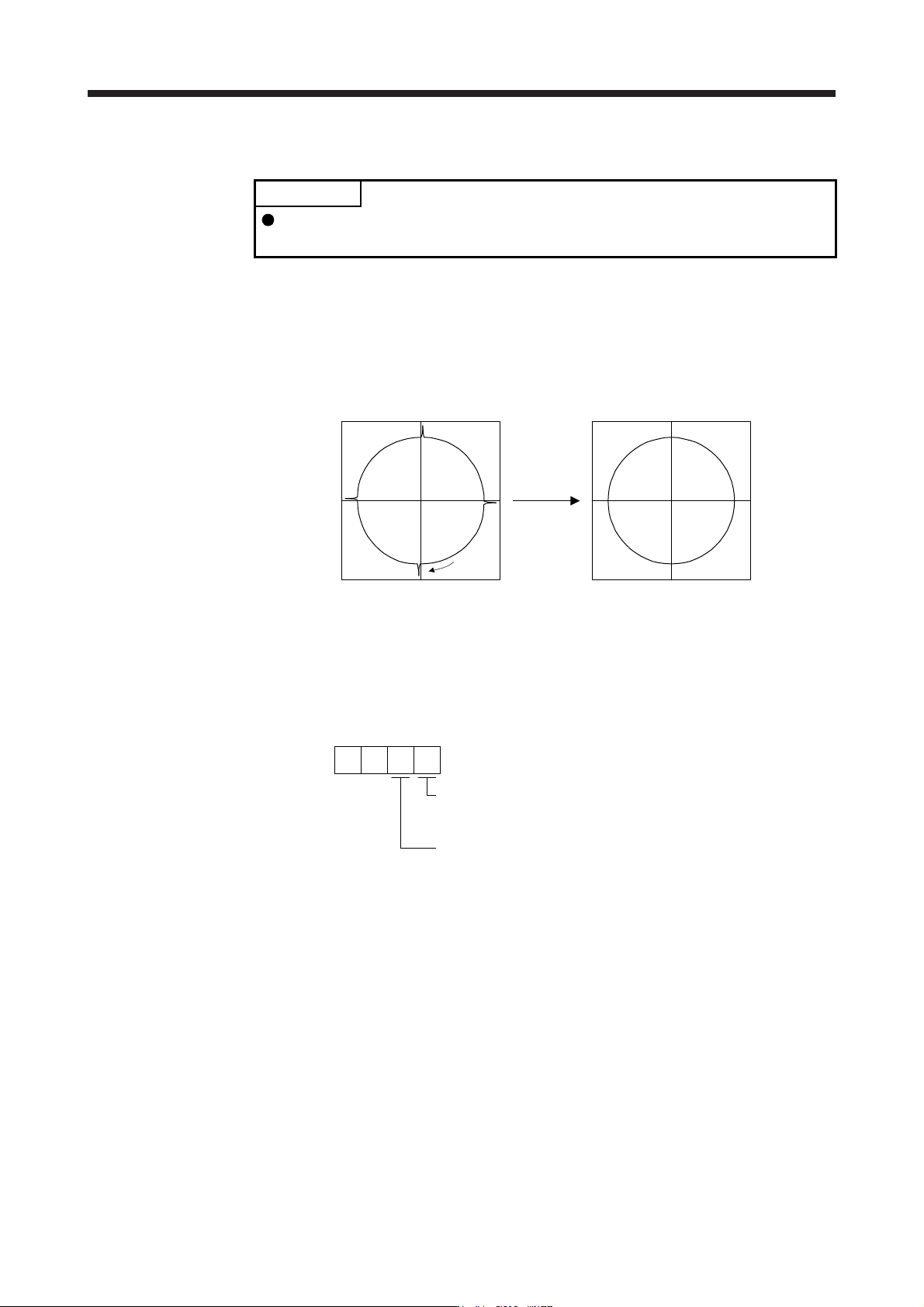
The lost motion compensation function corrects response delays (caused by a non-sensitive band due to
friction, twist, expansion, and backlash) caused when the machine travel direction is reversed. This function
contributes to improvement for protrusions that occur at a quadrant change and streaks that occur at a
quadrant change during circular cutting.
This function is effective when a high follow-up performance is required such as drawing an arc with an X-Y
table.
The locus before compensation The locus after compensation
Compensation
Travel
direction
(1) Parameter setting
Setting [Pr. PE44] to [Pr. PE50] enables the lost motion compensation function.
(a) Lost motion compensation function selection ([Pr. PE48])
Select the lost motion compensation function.
Lost motion compensation selection
0: Lost motion compensation disabled
1: Lost motion compensation enabled
0
Unit setting of lost motion compensation non-sensitive band
0: 1 pulse unit
1: 1 kpulse unit
[Pr. PE48]
0
(b) Lost motion compensation ([Pr. PE44]/[Pr. PE45])
Set the same value for the lost motion compensation for each of when the forward rotation switches
to the reverse rotation and when the reverse rotation switches to the forward rotation. When the
heights of protrusions differ depending on the travel direction, set the different compensation for
each travel direction. Set a value twice the usual friction torque and adjust the value while checking
protrusions.
(c) Torque offset ([Pr. PE47])
For a vertical axis, unbalanced torque occurs due to the gravity. Although setting the torque offset is
usually unnecessary, setting unbalanced torque of a machine as a torque offset cancels the
unbalanced torque. The torque offset does not need to be set for a machine not generating
unbalanced torque. The torque offset cannot be used for linear servo motors and direct drive motors.
Set 0.00%.