sh030106u.pdf - 第201页
5. PARAMETE RS 5 - 56 No. Sym bol Name and function Initial value [unit] Setting range PL17 LTSTS Magnet ic pole detect ion - Minute posit ion detection method - Function s election To enable t he parameter, select "…

5. PARAMETERS
5 - 55
No. Symbol Name and function
Initial
value
[unit]
Setting
range
PL08 *LIT3 Linear servo motor/DD motor function selection 3
Refer to the
"Name and
function" column.
Setting
digit
Explanation
Initial
value
_ _ _ x
Magnetic pole detection method selection
0: Position detection method
4: Minute position detection method
0h
_ _ x _ For manufacturer setting 1h
_ x _ _
Magnetic pole detection - Stroke limit enabled/disabled selection
0: Enabled
1: Disabled
0h
x _ _ _
Minute position detection method - High-resolution encoder
selection
0: Disabled
1: Enabled
This digit will be enabled when "minute position detection method"
is selected in [Pr. PL08 (_ _ _ x)].
If a linear encoder whose resolution is smaller than 0.05 μm is used
and also [AL. 27 Initial magnetic pole detection error] occurs
because the travel distance at magnetic pole detection is too large
or vibration occurs, set "1" (enabled).
This digit is available on servo amplifiers with software version A8
or later.
0h
PL09 LPWM Magnetic pole detection voltage level
This is used to set a direct current exciting voltage level during the magnetic pole detection.
If [AL. 32 Overcurrent], [AL. 50 Overload 1], or [AL. 51 Overload 2] occurs during the magnetic
pole detection, decrease the setting value.
If [AL. 27 Initial magnetic pole detection error] occurs during the magnetic pole detection,
increase the setting value.
30
[%]
0 to 100
5. PARAMETERS
5 - 56
No. Symbol Name and function
Initial
value
[unit]
Setting
range
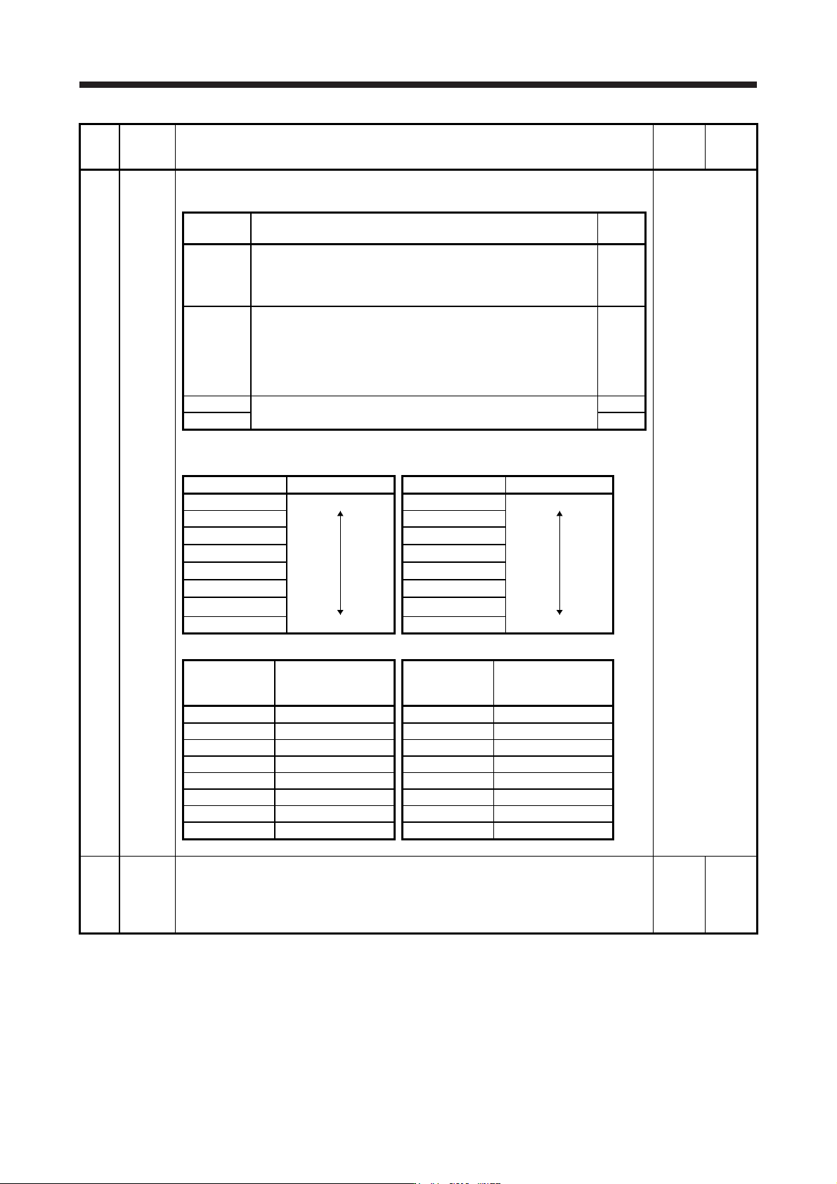
PL17 LTSTS Magnetic pole detection - Minute position detection method - Function selection
To enable the parameter, select "Minute position detection method (_ _ _ 4)" in [Pr. PL08].
Refer to the
"Name and
function" column.
Setting
digit
Explanation
Initial
value
_ _ _ x Response selection
Set a response of the minute position detection method.
When reducing a travel distance at the magnetic pole detection,
increase the setting value. Refer to table 5.9 for settings.
0h
_ _ x _ Load to motor mass ratio/load to motor inertia ratio selection
Select a load to mass of the linear servo motor primary-side ratio or
load to mass of the direct drive motor inertia ratio used at the
minute position detection method. Set a closest value to the actual
load.
Refer to table 5.10 for settings.
0h
_ x _ _ For manufacturer setting 0h
x _ _ _ 0h
Table 5.9 Response of minute position detection method at magnetic
pole detection
Setting value Response Setting value Response
_ _ _ 0 Low response _ _ _ 8 Middle response
_ _ _ 1
_ _ _ 9
_ _ _ 2 _ _ _ A
_ _ _ 3 _ _ _ B
_ _ _ 4 _ _ _ C
_ _ _ 5 _ _ _ D
_ _ _ 6 _ _ _ E
_ _ _ 7 Middle response _ _ _ F High response
Table 5.10 Load to motor mass ratio/load to motor inertia ratio
Setting value
Load to motor mass
ratio/load to motor
inertia ratio
Setting value
Load to motor mass
ratio/load to motor
inertia ratio
_ _ 0 _ 10 times or less _ _ 8 _ 80 times
_ _ 1 _ 10 times _ _ 9 _ 90 times
_ _ 2 _ 20 times _ _ A _ 100 times
_ _ 3 _ 30 times _ _ B _ 110 times
_ _ 4 _ 40 times _ _ C _ 120 times
_ _ 5 _ 50 times _ _ D _ 130 times
_ _ 6 _ 60 times _ _ E _ 140 times
_ _ 7 _ 70 times _ _ F _ 150 times or more
PL18 IDLV Magnetic pole detection - Minute position detection method - Identification signal amplitude
Set an identification signal amplitude used in the minute position detection method.
This parameter is enabled only when the magnetic pole detection is the minute position
detection method.
However, setting "0" will be 100% amplitude.
0
[%]
0 to 100

6. NORMAL GAIN ADJUSTMENT
6 - 1
6. NORMAL GAIN ADJUSTMENT
POINT
In the torque control mode, you do not need to make gain adjustment.
Before making gain adjustment, check that your machine is not being operated
at maximum torque of the servo motor. If operated over maximum torque, the
machine may vibrate and may operate unexpectedly. In addition, make gain
adjustment with a safety margin considering characteristic differences of each
machine. It is recommended that generated torque during operation is under
90% of the maximum torque of the servo motor.
When you use a linear servo motor, replace the following words in the left to the
words in the right.
Load to motor inertia ratio → Load to motor mass ratio
Torque → Thrust
(Servo motor) speed → (Linear servo motor) speed
For the vibration suppression control tuning mode, the setting range of [Pr.
PB07] is limited. For the vibration suppression control tuning mode, the setting
range of [Pr. PB07] is limited. Refer to section 7.1.5 (4) for details.
6.1 Different adjustment methods
6.1.1 Adjustment on a single servo amplifier
The following table shows the gain adjustment modes that can be set on a single servo amplifier. For gain
adjustment, first execute "Auto tuning mode 1". If you are not satisfied with the result of the adjustment,
execute "Auto tuning mode 2" and "Manual mode" in this order.
(1) Gain adjustment mode explanation
Gain adjustment mode [Pr. PA08] setting
Estimation of load to motor
inertia ratio
Automatically set
parameters
Manually set
parameters
Auto tuning mode 1
(initial value)
_ _ _ 1 Always estimated GD2 ([Pr. PB06])
PG1 ([Pr. PB07])
PG2 ([Pr. PB08])
VG2 ([Pr. PB09])
VIC ([Pr. PB10])
RSP ([Pr. PA09])
Auto tuning mode 2 _ _ _ 2 Fixed to [Pr. PB06] value PG1 ([Pr. PB07])
PG2 ([Pr. PB08])
VG2 ([Pr. PB09])
VIC ([Pr. PB10])
GD2 ([Pr. PB06])
RSP ([Pr. PA09])
Manual mode _ _ _ 3 GD2 ([Pr. PB06])
PG1 ([Pr. PB07])
PG2 ([Pr. PB08])
VG2 ([Pr. PB09])
VIC ([Pr. PB10])
2 gain adjustment mode 1
(interpolation mode)
_ _ _ 0 Always estimated GD2 ([Pr. PB06])
PG2 ([Pr. PB08])
VG2 ([Pr. PB09])
VIC ([Pr. PB10])
PG1 ([Pr. PB07])
RSP ([Pr. PA09])
2 gain adjustment mode 2 _ _ _ 4 Fixed to [Pr. PB06] value PG2 ([Pr. PB08])
VG2 ([Pr. PB09])
VIC ([Pr. PB10])
GD2 ([Pr. PB06])
PG1 ([Pr. PB07])
RSP ([Pr. PA09])