sh030106u.pdf - 第191页
5. PARAMETE RS 5 - 46 No. Sym bol Name and function Initial value [unit] Setting range PD16 *MD1 Driv er communication s etting - Master - Transmit dat a selection 1 This parameter is used to sel ect transmit dat a from …
5. PARAMETERS
5 - 45
No. Symbol Name and function
Initial
value
[unit]
Setting
range
PD14 *DOP3 Function selection D-3
Refer to the
"Name and
function" column.
Setting
digit
Explanation
Initial
value
_ _ _ x For manufacturer setting 0h
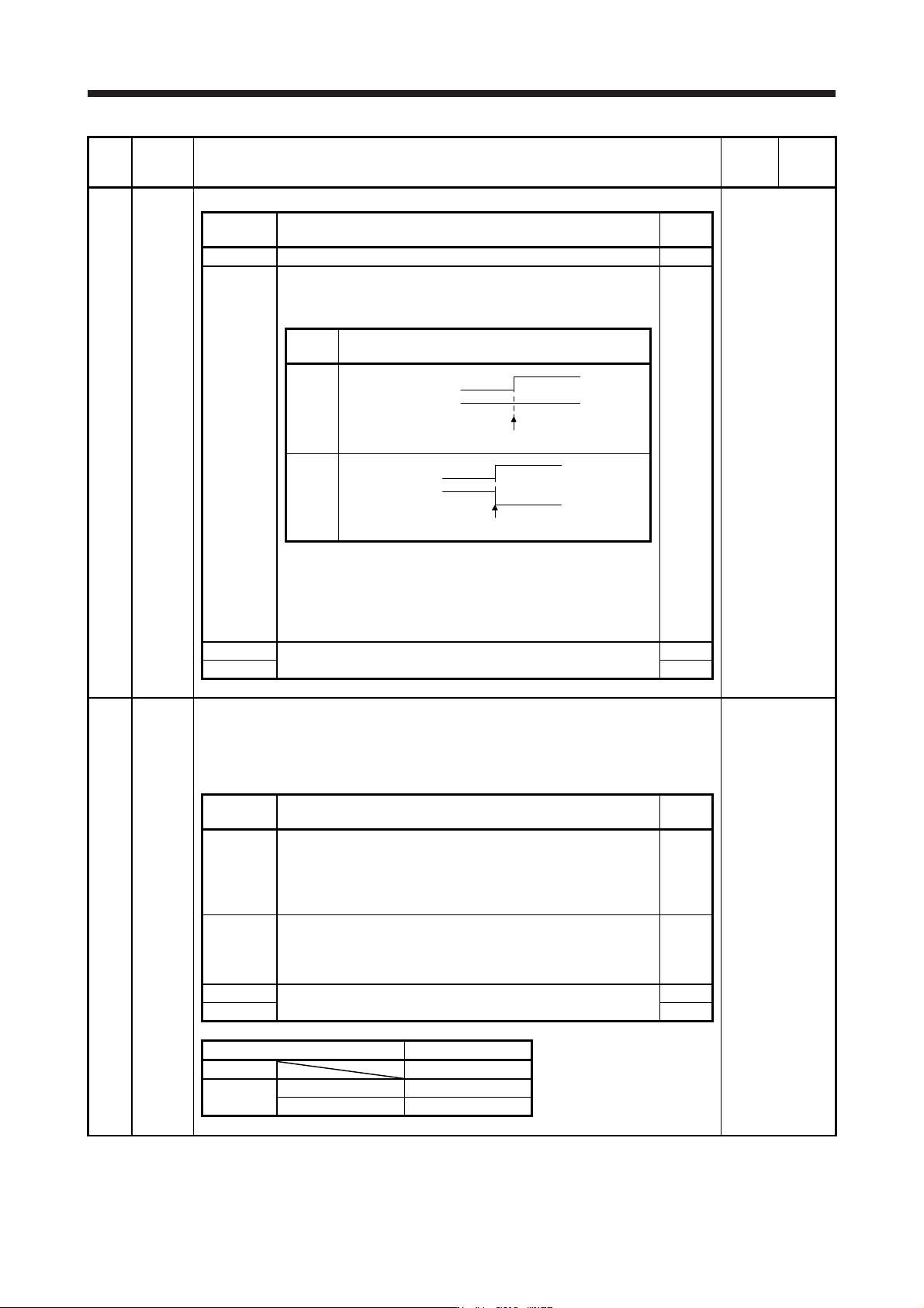
_ _ x _ Selection of output device at warning occurrence
Select WNG (Warning) and ALM (Malfunction) output status at
warning occurrence.
0h
Setting
value
(Note 1) Device status
0
0
1
0
1
W
NG
A
LM
Warning occurrence
1
0
1
0
1
WNG
ALM
Warning occurrence (Note 2)
Note 1. 0: Off
1: On
2.
A
lthough ALM is turned off upon occurrence of the
warning, the forced stop deceleration is performed.
_ x _ _ For manufacturer setting 0h
x _ _ _ 0h
PD15 *IDCS Driver communication setting
This parameter is used to select master/slave axis for the driver communication.
This is available only when the forced stop deceleration function is disabled. When the forced
stop deceleration function is enabled, [AL. 37] will occur.
This parameter setting is used with servo amplifier with software version A8 or later.
Refer to the
"Name and
function" column.
Setting
digit
Explanation
Initial
value
_ _ _ x Master axis operation selection
Setting "1" other than in standard control mode and fully closed
loop control mode will trigger [AL. 37].
0: Disabled (not using master-slave operation function)
1: Enabled (this servo amplifier: master axis)
0h
_ _ x _ Slave axis operation selection
Setting "1" other than in standard control mode will trigger [AL. 37].
0: Disabled (not using master-slave operation function)
1: Enabled (this servo amplifier: slave axis)
0h
_ x _ _ For manufacturer setting 0h
x _ _ _ 0h
Master-slave operation function Setting value
Not used 0000
Used
Master 0001
Slave 0010
5. PARAMETERS
5 - 46
No. Symbol Name and function
Initial
value
[unit]
Setting
range
PD16 *MD1 Driver communication setting - Master - Transmit data selection 1
This parameter is used to select transmit data from master axis to slave axis.
When setting this amplifier as master axis ([Pr. PD15] is "_ _ 0 1".), select "_ _ 3 8 (torque
command)" with this parameter.
This parameter setting is used with servo amplifier with software version A8 or later.
Refer to the
"Name and
function" column.
Setting
digit
Explanation
Initial
value
_ _ x x Transmission data selection
00: Disabled
38: Torque command
00h
_ x _ _ For manufacturer setting 0h
x _ _ _ 0h
PD17 *MD2 Driver communication setting - Master - Transmit data selection 2
This parameter is used to select transmit data from master axis to slave axis.
When setting this amplifier as master axis ([Pr. PD15] is "_ _ 0 1".), select "_ _ 3 A (speed limit
command)" with this parameter.
This parameter setting is used with servo amplifier with software version A8 or later.
Refer to the
"Name and
function" column.
Setting
digit
Explanation
Initial
value
_ _ x x Transmission data selection
00: Disabled
3A: speed limit command
00h
_ x _ _ For manufacturer setting 0h
x _ _ _ 0h
PD20 *SLA1 Driver communication setting - Slave - Master axis No. selection 1
Select a master axis when this amplifier is slave axis.
When setting this amplifier as slave axis ([Pr. PD15] is "_ _ 1 0".), set the axis No. of the servo
amplifier of master. Refer to section 4.3.1 for details of axis Nos. Setting "0" disables this
parameter.
This parameter setting is used with servo amplifier with software version A8 or later.
0 0 to 32
PD30 TLC Master-slave operation - Torque command coefficient on slave
This parameter is used to set a internal torque command coefficient to torque command value
received from master axis.
This parameter is enabled when this amplifier is set as slave axis ([Pr. PD15] is "_ _ 1 0".).
The maximum value is 500. Setting over 500 will be 500.
Setting 100 [%] means multiplication of one. The torque ratio will be 100 (master) to 100
(slave).
Setting 90 [%] means multiplication of 0.9. The torque ratio will be 100 (master) to 90 (slave).
This parameter setting is used with servo amplifier with software version A8 or later.
0 [%] 0 to 500
5. PARAMETERS
5 - 47
No. Symbol Name and function
Initial
value
[unit]
Setting
range
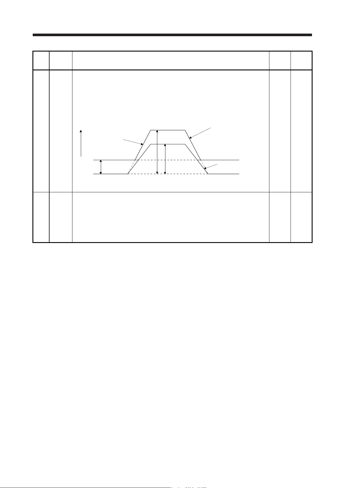
PD31 VLC Master-slave operation - Speed limit coefficient on slave
This parameter is used to set a internal speed limit value coefficient to speed limit command
value received from master axis.
This parameter is enabled when this amplifier is set as slave axis ([Pr. PD15] is "_ _ 1 0".).
The maximum value is 500. Setting over 500 will be 500.
Setting 100 [%] means multiplication of one.
Setting example: [Pr. PD31 (VLC)] = 140 [%], [Pr. PD32 (VLL)] = 300 [r/min], and master side
acceleration/deceleration at 1000 [r/min]
0 [%] 0 to 500
VLL
0
Speed command from
master side × VLC [%]
Speed limit value o
f
slave side
300 r/min
1400 r/min
1000 r/min
Speed limit command
from master side (drive
r
communication)
Speed (r/min)
This parameter setting is used with servo amplifier with software version A8 or later.
PD32 VLL Master-slave operation - Speed limit adjusted value on slave
This parameter is used to set a minimum value for internal speed limit value.
This parameter is enabled when this amplifier is set as slave axis ([Pr. PD15] is "_ _ 1 0".).
The speed limit value will not be this setting value or lower.
This parameter ensures torque control range at low speed driving (avoid area likely to reach
speed limit). Set 100 to 500 [r/min] normally as a reference.
Refer to [Pr. PD31] for the setting example.
This parameter setting is used with servo amplifier with software version A8 or later.
0 [r/min]
0 to
32767