sh030106u.pdf - 第474页
14. USIN G A LINEAR SER VO MOTOR 14 - 7 CAUTION Before wir ing, s witch operation , etc., eliminat e stat ic elec tri city. O therwise, it may cause a m alfuncti on. Connectin g a linear servo motor for differe nt axis t…
14. USING A LINEAR SERVO MOTOR
14 - 6
14.2 Signals and wiring
WARNING
Any person who is involved in wiring should be fully competent to do the work.
Before wiring, turn off the power and wait for 15 minutes or more until the charge
lamp turns off. Then, confirm that the voltage between P+ and N- is safe with a
voltage tester and others. Otherwise, an electric shock may occur. In addition,
when confirming whether the charge lamp is off or not, always confirm it from the
front of the servo amplifier.
Ground the servo amplifier and the linear servo motor securely.
Do not attempt to wire the servo amplifier and the linear servo motor until they
have been installed. Otherwise, it may cause an electric shock.
The cables should not be damaged, stressed, loaded, or pinched. Otherwise, it
may cause an electric shock.
To avoid an electric shock, insulate the connections of the power supply terminals.
CAUTION
Wire the equipment correctly and securely. Otherwise, the linear servo motor may
operate unexpectedly, resulting in injury.
Connect cables to the correct terminals. Otherwise, a burst, damage, etc. may
occur.
Ensure that polarity (+/-) is correct. Otherwise, a burst, damage, etc. may occur.
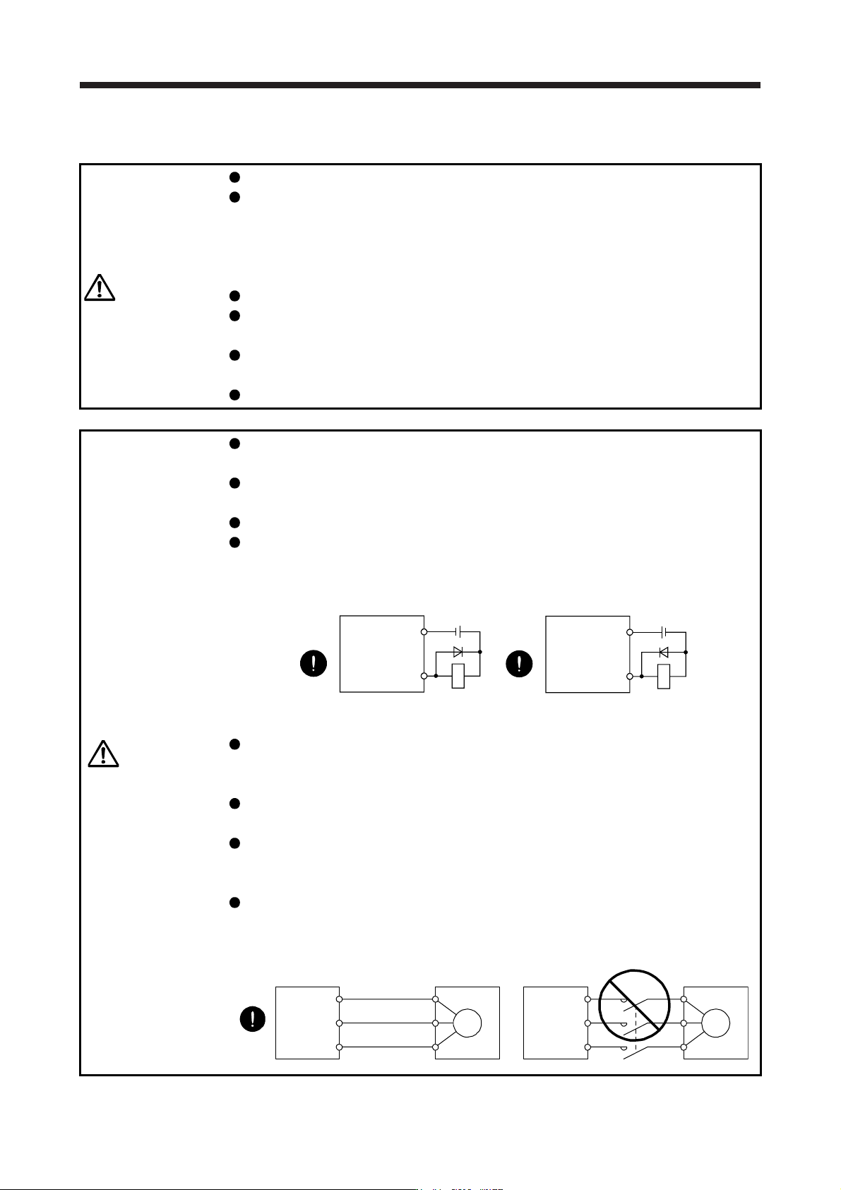
The surge absorbing diode installed to the DC relay for control output should be
fitted in the specified direction. Otherwise, the emergency stop and other
protective circuits may not operate.
DOCOM
24 V DC
Servo amplifier
RA
For sink output interface
Control output
signal
DOCOM
Control output
signal
24 V DC
Servo amplifier
RA
For source output interface
Use a noise filter, etc. to minimize the influence of electromagnetic interference.
Electromagnetic interference may be given to the electronic equipment used near
the servo amplifier.
Do not install a power capacitor, surge killer or radio noise filter (optional FR-BIF(-
H)) with the power wire of the linear servo motor.
When using the regenerative resistor, switch power off with the alarm signal.
Otherwise, a transistor fault or the like may overheat the regenerative resistor,
causing a fire.
Connect the servo amplifier power output (U/V/W) to the linear servo motor power
input (U/V/W) directly. Do not let a magnetic contactor, etc. intervene. Otherwise,
it may cause a malfunction.
Servo amplifier Servo amplifier
Linear servo
motor
Linear servo
motor
U
M
V
W
U
V
W
U
M
V
W
U
V
W
14. USING A LINEAR SERVO MOTOR
14 - 7
CAUTION
Before wiring, switch operation, etc., eliminate static electricity. Otherwise, it may
cause a malfunction.
Connecting a linear servo motor for different axis to the U, V, W, or CN2 may
cause a malfunction.
Do not modify the equipment.
The cables such as power wires deriving from the primary side cannot stand the
long-term bending action. Avoid the bending action by fixing the cables to the
moving part, etc. Also, use the cable that stands the long-term bending action for
the wiring to the servo amplifier.
This chapter does not describe the following items. For details of the items, refer to each section of the
detailed description field.
Item Detailed explanations
Input power supply circuit Section 3.1
Explanation of power supply system Section 3.3
Signal (device) explanations Section 3.5
Alarm occurrence timing chart Section 3.7
Interfaces Section 3.8
SSCNET III cable connection Section 3.9
Grounding Section 3.11
Switch setting and display of the servo
amplifier
Section 4.3
14. USING A LINEAR SERVO MOTOR
14 - 8
14.3 Operation and functions
14.3.1 Startup
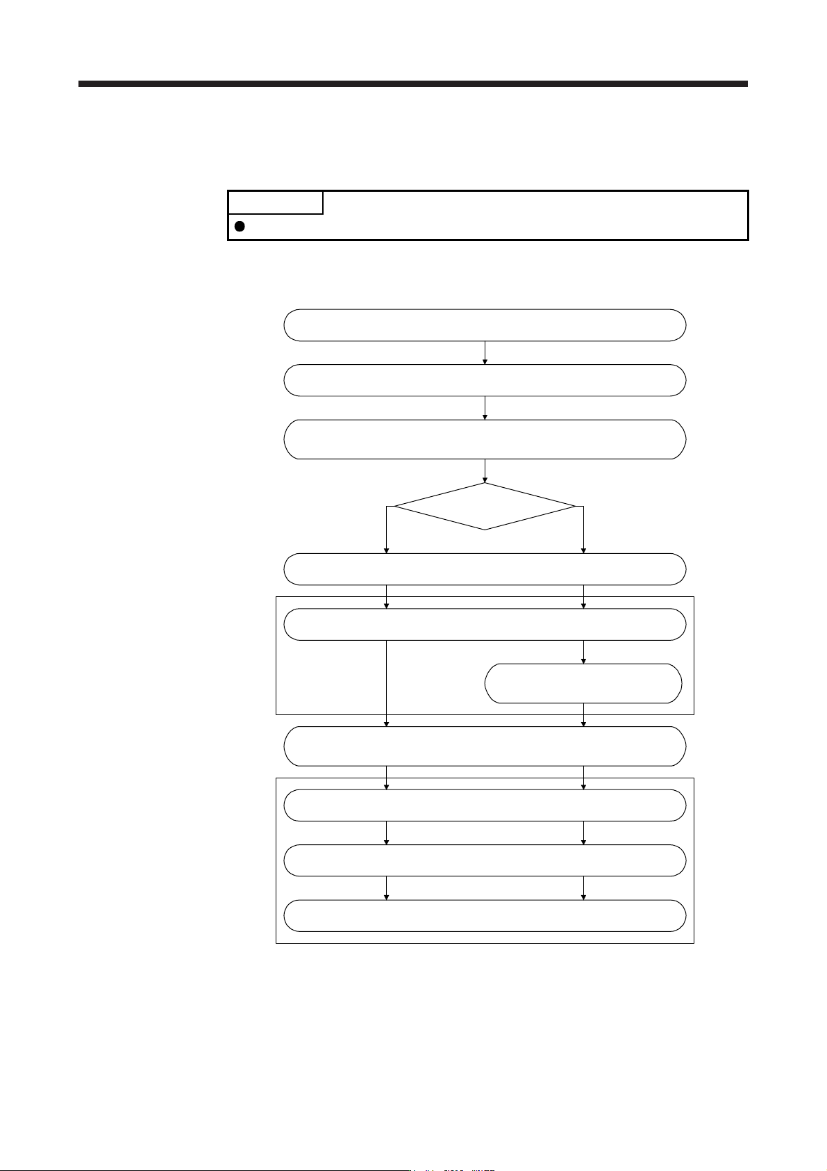
POINT
When using the linear servo motor, set [Pr. PA01] to "_ _ 4 _".
(1) Startup procedure
Start up the linear servo system in the following procedure.
Set the linear servo motor series and linear servo motor type.
(Refer to (2) in this section.)
(Note)
Set the linear encoder direction and the linear servo motor direction.
(Refer to (3) in this section.)
(Note)
Set the linear encoder resolution. (Refer to (4) in this section.)
Change the setting to disable the
magnetic pole detection.
(Refer to (3) of section 14.3.2.)
What is the type of the
linear encoder?
Installation and wiring
(Note)
Perform the magnetic pole detection. (Refer to (3) of section 14.3.2.)
(Note)
Positioning operation check using the test operation mode
(Refer to section 14.3.4.)
Positioning operation check using the controller (Refer to section 14.3.5.)
Home position return operation (Refer to section 14.3.3.)
Positioning operation
Incremental linear encoder Absolute position linear encoder
Note. Use MR Confi
g
urator2.
(2) Set the linear servo motor series and linear servo motor type.
To use the linear servo motor, set the linear servo motor series and linear servo motor type with [Pr.
PA17 Servo motor series setting] and [Pr. PA18 Servo motor type setting]. (Refer to section 5.2.1.)