sh030106u.pdf - 第406页
11. OPT I ONS AND PER IPH ERA L EQU IPM ENT 11 - 8 5 11.14 Noi se red uction tec hniques Noises are c lass ified int o ex ternal noises w hich enter t he serv o ampl ifier to ca use it to malfunc tion an d those radiated…
11. OPTIONS AND PERIPHERAL EQUIPMENT
11 - 84
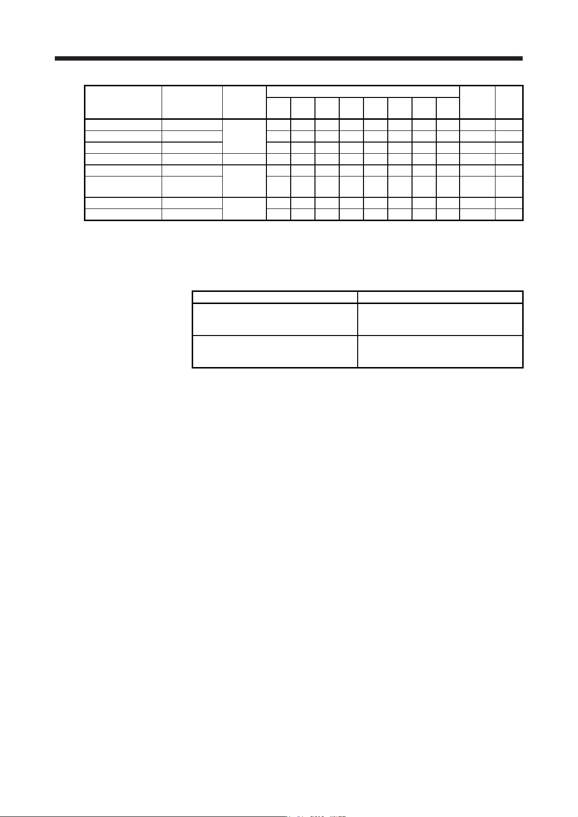
Servo amplifier
Power factor
improving AC
reactor
Dimensions
Dimensions [mm]
Terminal
size
Mass
[kg]
W W1 W2 H
D
(Note)
D1 D2 d
MR-J4-60B4(-RJ) FR-HAL-H1.5K
Fig. 11.11
135 120 8 115 59 59.6 45 M4 M3.5 1.5
MR-J4-100B4(-RJ) FR-HAL-H2.2K 135 120 8 115 59 59.6 45 M4 M3.5 1.5
MR-J4-200B4(-RJ) FR-HAL-H3.7K 135 120 8 115 69 70.6 57 M4 M3.5 2.5
MR-J4-350B4(-RJ) FR-HAL-H7.5K Fig. 11.12 160 145 8 150 91 91 75 M4 M4 5.0
MR-J4-500B4(-RJ) FR-HAL-H11K
Fig. 11.13
160 145 8 146 91 91 75 M4 M5 6.0
MR-J4-700B4(-RJ)
MR-J4-11KB4(-RJ)
FR-HAL-H15K 220 200 10 195 105 90 70 M5 M5 9.0
MR-J4-15KB4(-RJ) FR-HAL-H22K
Fig. 11.14
220 200 10 212 155 90 70 M5 M5 9.5
MR-J4-22KB4(-RJ) FR-HAL-H30K 220 200 10 212 153 96 75 M5 M5 11
Note. Maximum dimensions. The dimension varies dependin
g
on the input/output lines.
11.13 Relay (recommended)
The following relays should be used with the interfaces
Interface Selection example
Digital input (interface DI-1)
Relay used for digital input command signals
To prevent defective contacts, use a relay for
small signal (twin contacts).
(Ex.) Omron : type G2A, MY
Digital output (interface DO-1)
Relay used for digital output signals
Small relay with 12 V DC or 24 V DC of rated
current 40 mA or less
(Ex.) Omron : type MY
11. OPTIONS AND PERIPHERAL EQUIPMENT
11 - 85
11.14 Noi
se reduction techniques
Noises are classified into external noises which enter the servo amplifier to cause it to malfunction and those
radiated by the servo amplifier to cause peripheral equipment to malfunction. Since the servo amplifier is an
electronic device which handles small signals, the following general noise reduction techniques are required.
Also, the servo amplifier can be a source of noise as its outputs are chopped by high carrier frequencies. If
peripheral equipment malfunctions due to noises produced by the servo amplifier, noise suppression
measures must be taken. The measures will vary slightly with the routes of noise transmission.
(1) Noise reduction techniques
(a) General reduction techniques
Avoid bundling power lines (input/output) and signal cables together or running them in parallel to
each other. Separate the power lines from the signal cables.
Use a shielded twisted pair cable for connection with the encoder and for control signal
transmission, and connect the external conductor of the cable to the SD terminal.
Ground the servo amplifier, servo motor, etc. together at one point. (Refer to section 3.11.)
(b) Reduction techniques for external noises that cause the servo amplifier to malfunction
If there are noise sources (such as a magnetic contactor, an electromagnetic brake, and many relays
which make a large amount of noise) near the servo amplifier and the servo amplifier may
malfunction, the following countermeasures are required.
Provide surge absorbers on the noise sources to suppress noises.
Attach data line filters to the signal cables.
Ground the shields of the encoder connecting cable and the control signal cables with cable clamp
fittings.
Although a surge absorber is built into the servo amplifier, to protect the servo amplifier and other
equipment against large exogenous noise and lightning surge, attaching a varistor to the power
input section of the equipment is recommended.
(c) Techniques for noises radiated by the servo amplifier that cause peripheral equipment to malfunction
Noises produced by the servo amplifier are classified into those radiated from the cables connect
ed
to the servo amplifier and its main circuits (input and output circuits), those induced
electromagnetically or statically by the signal cables of the peripheral equipment located near the
mai
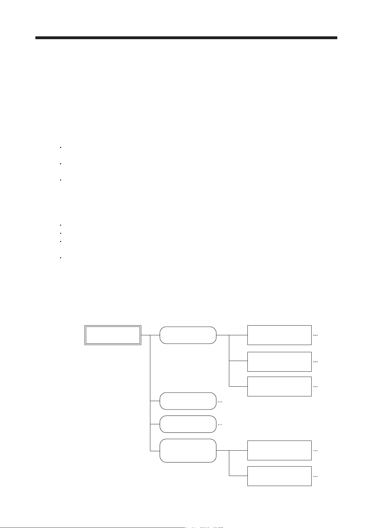
n circuit cables, and those transmitted through the power supply cables.
Noises produced
by servo amplifier
Noises transmitted
in the air
Noise radiated directly
from servo amplifier
Magnetic induction
noise
Static induction
noise
Noises transmitted
through electric
channels
Noise radiated from the
power supply cable
Noise radiated from
servo motor cable
Noise transmitted through
power supply cable
Noise sneaking from
grounding cable due to
leakage current
Routes 4) and 5)
Route 1)
Route 2)
Route 3)
Route 7)
Route 8)
Route 6)
11. OPTIONS AND PERIPHERAL EQUIPMENT
11 - 86
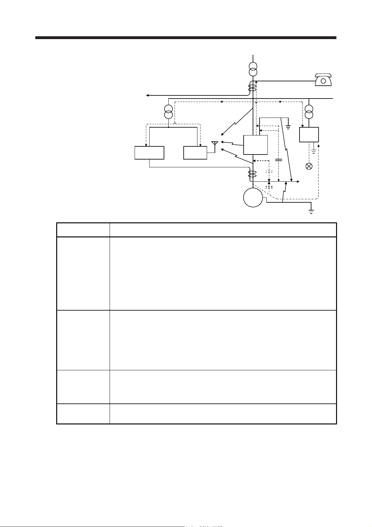
Instrument Receiver
Servo
amplifier
Servo motor M
2)
2)
8)
1)
7)
7) 7)
5)
3)
4)
6)
3)
Sensor
power
supply
Sensor
Noise transmission
route
Suppression techniques
1) 2) 3)
When measuring instruments, receivers, sensors, etc. which handle weak signals and may
malfunction due to noise and/or their signal cables are contained in a cabinet together with the servo
amplifier or run near the servo amplifier, such devices may malfunction due to noises transmitted
through the air. The following techniques are required.
1. Provide maximum clearance between easily affected devices and the servo amplifier.
2. Provide maximum clearance between easily affected signal cables and the I/O cables of the servo
amplifier.
3. Avoid wiring the power lines (input/output lines of the servo amplifier) and signal lines side by side
or bundling them together.
4. Insert a line noise filter to the I/O cables or a radio noise filter on the input line.
5. Use shielded wires for the signal and power lines, or put the lines in separate metal conduits.
4) 5) 6)
When the power lines and the signal lines are laid side by side or bundled together, magnetic
induction noise and static induction noise will be transmitted through the signal cables and
malfunction may occur. The following techniques are required.
1. Provide maximum clearance between easily affected devices and the servo amplifier.
2. Provide maximum clearance between easily affected signal cables and the I/O cables of the servo
amplifier.
3. Avoid wiring the power lines (input/output lines of the servo amplifier) and signal lines side by side
or bundling them together.
4. Use shielded wires for the signal and power lines, or put the lines in separate metal conduits.
7)
When the power supply of peripheral equipment is connected to the power supply of the servo
amplifier system, noises produced by the servo amplifier may be transmitted back through the power
supply cable and the devices may malfunction. The following techniques are required.
1. Install the radio noise filter (FR-BIF(-H)) on the power lines (Input lines) of the servo amplifier.
2. Install the line noise filter (FR-BSF01/FR-BLF) on the power lines of the servo amplifier.
8)
If the grounding wires of the peripheral equipment and the servo amplifier make a closed loop circuit,
leakage current may flow through, causing the equipment to malfunction. In this case, the
malfunction may be prevented by the grounding wires disconnected from the equipment.