sh030106u.pdf - 第45页
1. FUNCTI ONS AND CONF IGURATION 1 - 28 (e) MR-J4-11KB(-RJ)/MR-J4 -15KB(-RJ) POINT The servo ampl ifier is s hown w ithout th e front c over. F or remov al of the front cover, r efer to sect ion 1.7. 2. (1) (2) (4) (3) (…
1. FUNCTIONS AND CONFIGURATION
1 - 27
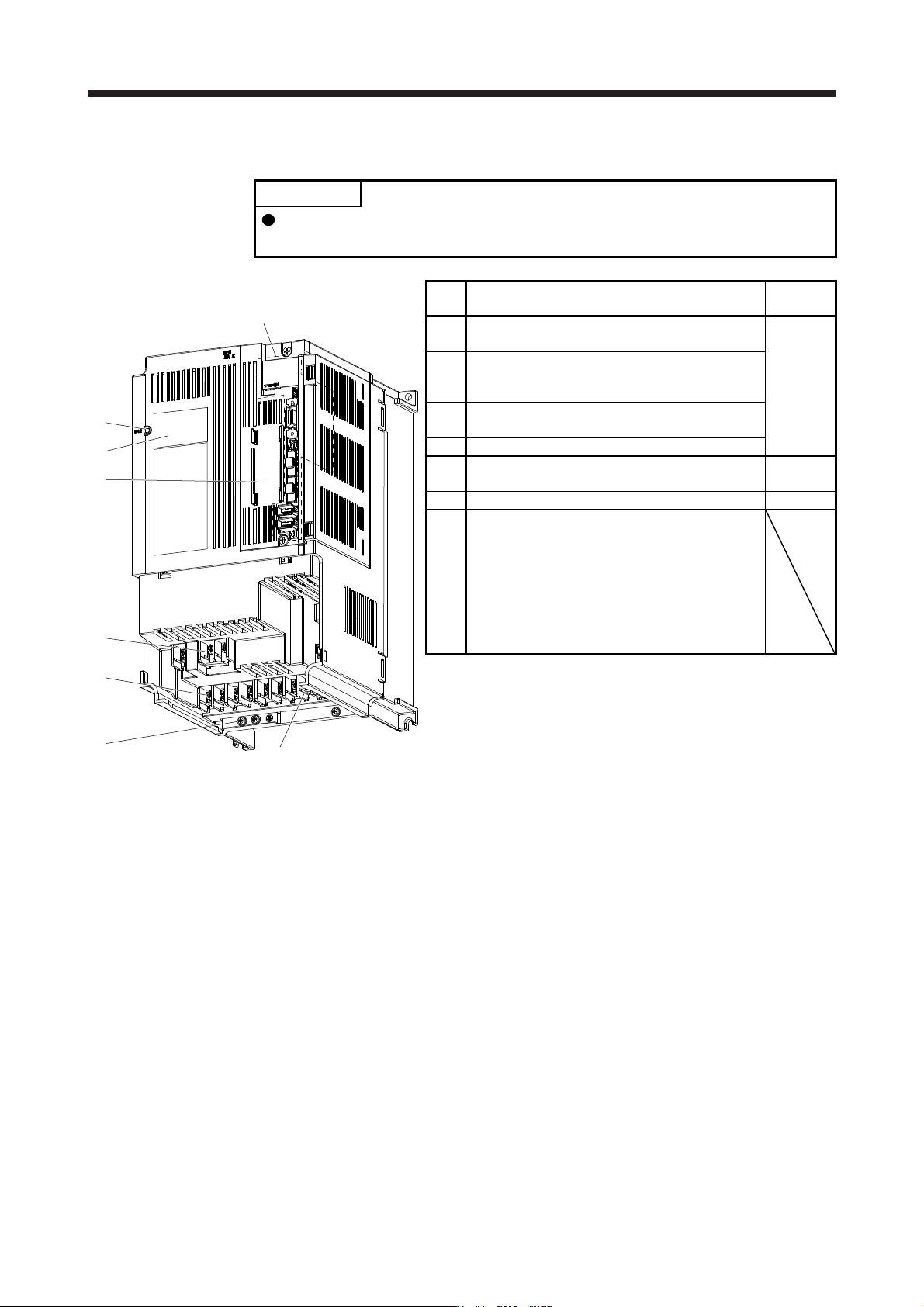
(d) MR-J4-700B(-RJ)
POINT
The servo amplifier is shown without the front cover. For removal of the front
cover, refer to section 1.7.2.
(1)
(5)
(Note)
(2)
(4)
(3)
(6)
The broken line area is the same as
MR-J4-200B4(-RJ) or less.
(7)
No. Name/Application
Detailed
explanation
(1)
Power factor improving reactor terminal block (TE3)
Used to connect the DC reactor.
Section 3.1
Section 3.3
(2)
Main circuit terminal block (TE1)
Used to connect the input power supply,
regenerative option, and servo motor.
(3)
Control circuit terminal block (TE2)
Used to connect the control circuit power supply.
(4) Protective earth (PE) terminal
(5)
Battery holder
Install the battery for absolute position data backup.
Section
12.2
(6) Rating plate Section 1.6
(7)
Charge lamp
When the main circuit is charged, this will light.
While this lamp is lit, do not reconnect the cables.
The lamp may light up when only the control circuit
is powered on. Before wiring or inspection, turn off
the main circuit power and the control circuit power,
and wait for 15 minutes or more until the charge
lamp turns off. Then, check the voltage between P+
and N- using the tester, etc.
Note. Lines for slots around the batter
y
holder are omitted from the illustration.
1. FUNCTIONS AND CONFIGURATION
1 - 28
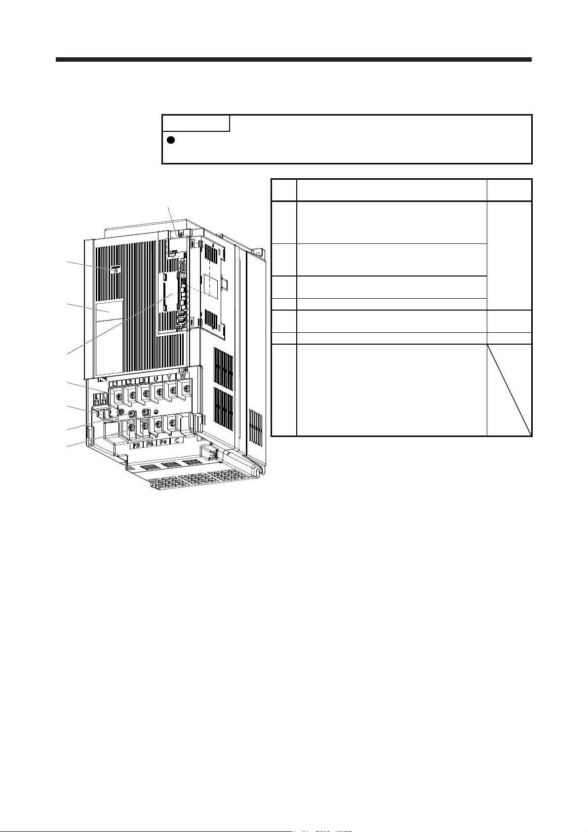
(e) MR-J4-11KB(-RJ)/MR-J4-15KB(-RJ)
POINT
The servo amplifier is shown without the front cover. For removal of the front
cover, refer to section 1.7.2.
(1)
(2)
(4)
(3)
(6)
The broken line area is the same as
MR-J4-200B(-RJ) or less.
(7)
(1)
(5)
(Note)
(2)
(4)
(3)
(6)
(7)
No. Name/Application
Detailed
explanation
(1)
Power factor improving reactor terminal block (TE1-
2)
Used to connect a power factor improving DC
reactor and a regenerative option.
Section 3.1
Section 3.3
(2)
Main circuit terminal block (TE1-1)
Used to connect the input power supply and servo
motor.
(3)
Control circuit terminal block (TE2)
Used to connect the control circuit power supply.
(4) Protective earth (PE) terminal
(5)
Battery holder
Install the battery for absolute position data backup.
Section
12.2
(6) Rating plate Section 1.6
(7)
Charge lamp
When the main circuit is charged, this will light.
While this lamp is lit, do not reconnect the cables.
The lamp may light up when only the control circuit
is powered on. Before wiring or inspection, turn off
the main circuit power and the control circuit power,
and wait for 15 minutes or more until the charge
lamp turns off. Then, check the voltage between P+
and N- using the tester, etc.
Note. Lines for slots around the batter
y
holder are omitted from the illustration.
1. FUNCTIONS AND CONFIGURATION
1 - 29
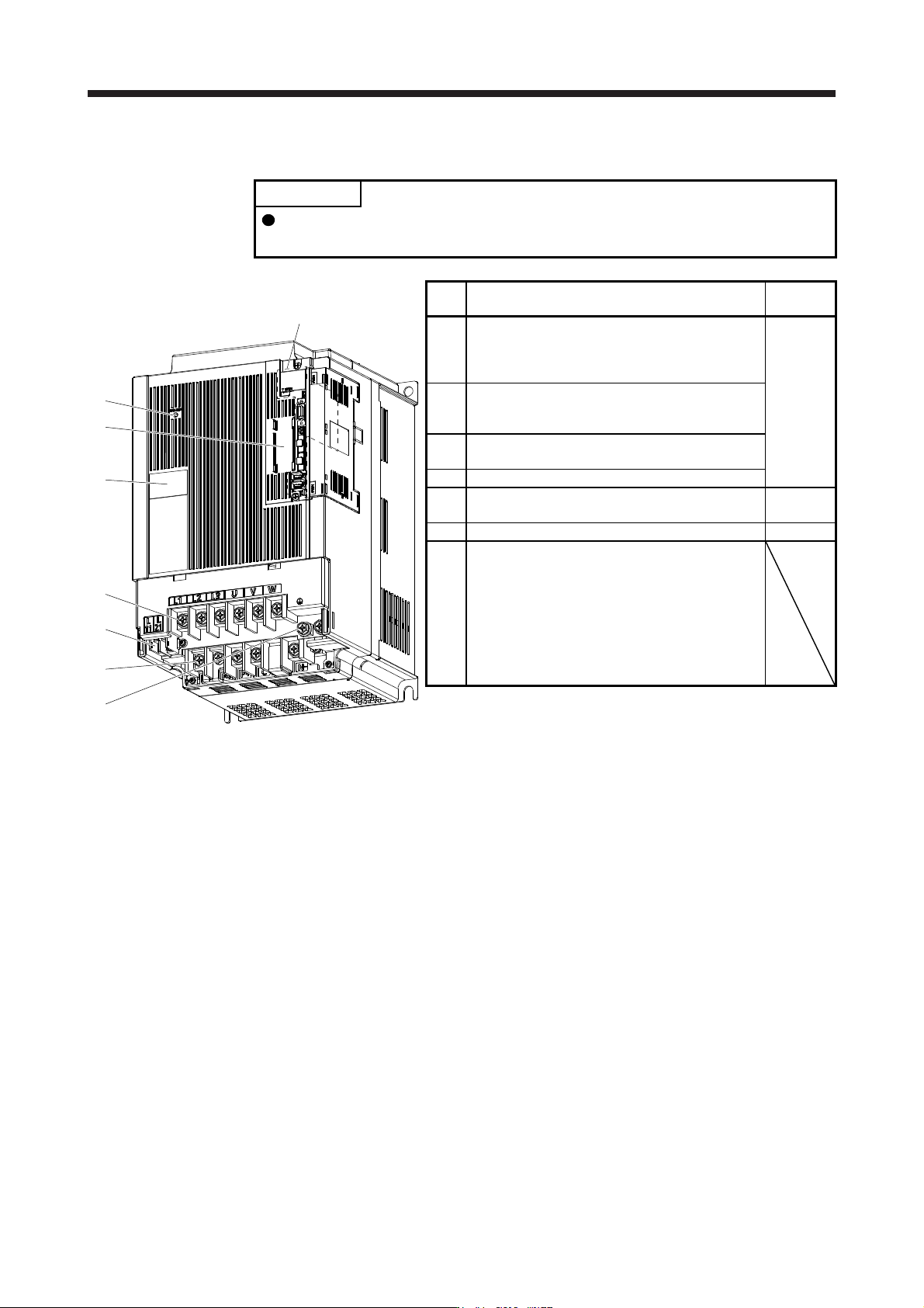
(f) MR-J4-22KB(-RJ)
POINT
The servo amplifier is shown without the front cover. For removal of the front
cover, refer to section 1.7.2.
(7)
(6)
(5)
(Note)
(2)
(3)
(4)
(1)
The broken line area is the same as
MR-J4-200B4(-RJ) or less.
No. Name/Application
Detailed
explanation
(1)
Power factor improving reactor terminal block (TE1-
2)
Used to connect a power factor improving DC
reactor and a regenerative option.
Section 3.1
Section 3.3
(2)
Main circuit terminal block (TE1-1)
Used to connect the input power supply and servo
motor.
(3)
Control circuit terminal block (TE2)
Used to connect the control circuit power supply.
(4) Protective earth (PE) terminal
(5)
Battery holder
Install the battery for absolute position data backup.
Section
12.2
(6) Rating plate Section 1.6
(7)
Charge lamp
When the main circuit is charged, this will light.
While this lamp is lit, do not reconnect the cables.
The lamp may light up when only the control circuit
is powered on. Before wiring or inspection, turn off
the main circuit power and the control circuit power,
and wait for 15 minutes or more until the charge
lamp turns off. Then, check the voltage between P+
and N- using the tester, etc.
Note. Lines for slots around the batter
y
holder are omitted from the illustration.