sh030106u.pdf - 第317页
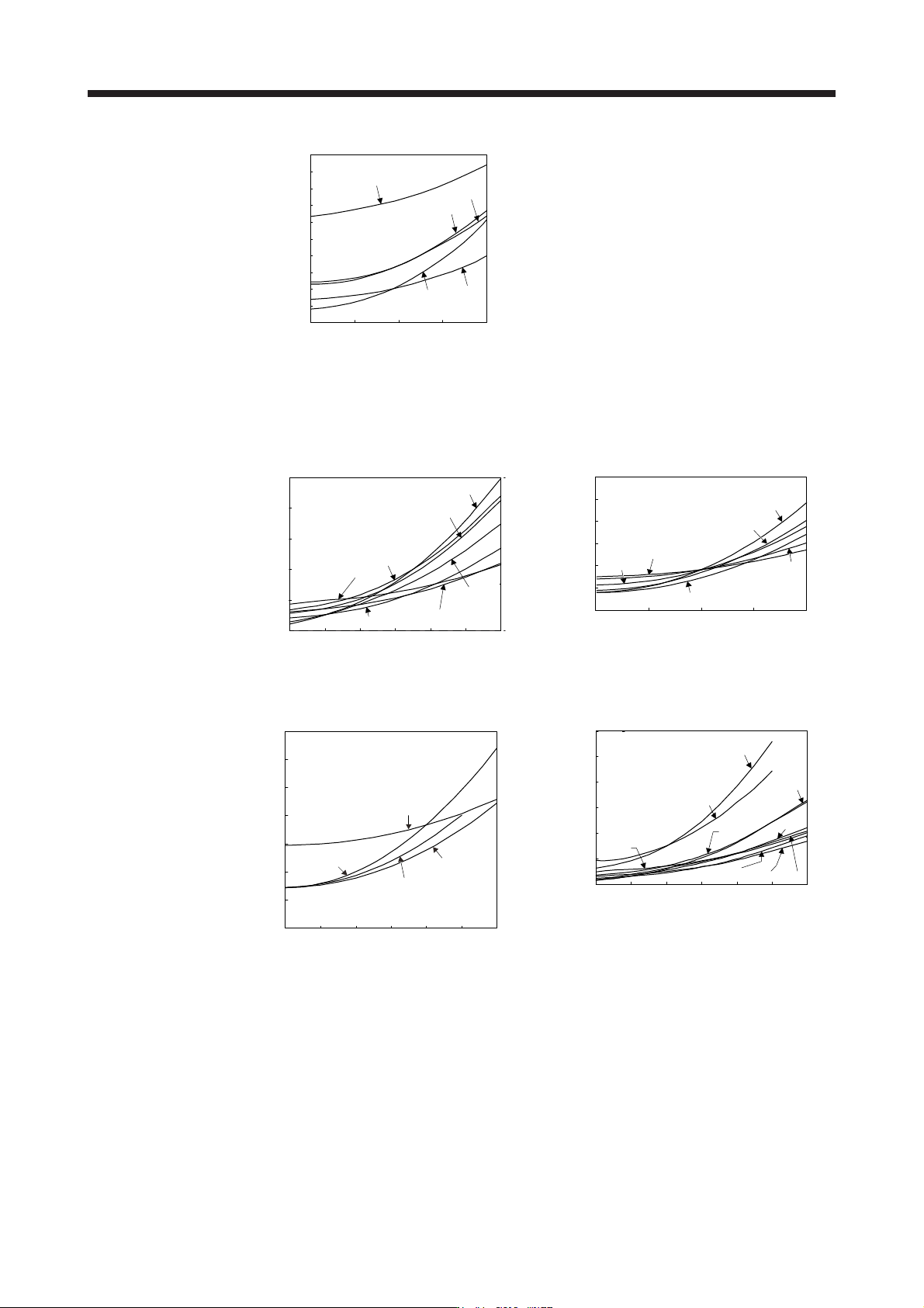
10. CHA RACT ERISTI CS 10 - 12 10.3.2 Per missi ble lo ad to motor inert ia when the dy namic br ake is used Use the dy namic br ake und er the load to mo tor iner tia r atio ind icated i n the fo llowing ta ble. If the …
10. CHARACTERISTICS
10 - 11
352
500 1000 1500 20000
0
10
20
30
40
50
60
70
80
90
100
502
72
202
152
Servo motor speed [r/min]
Dynamic brake time
constant τ [ms]
HG-UR series
(b) 400 V class
Speed [r/min]
0 500 1000
1500 2000 2500 3000
1524
5024
1024
524
100
80
60
40
20
0
2024
3524
7024
Dynamic brake time
constant
τ
[ms]
0
10
20
30
40
50
60
0 500 1000 1500 2000
6014
8014
25K14
12K14
20K14
15K14
Speed [r/min]
Dynamic brake time
constant τ [ms]
HG-SR series HG-JR1000 r/min series
Speed [r/min]
50
0
40
30
20
10
500 1000 1500 2000 2500 30000
11K1M4
22K1M4
15K1M4
701M4
70
60
Dynamic brake time
constant τ [ms]
Speed [r/min]
0 1000 2000
3000 4000 5000 6000
734
1534
5034
1034
534
120
100
80
60
40
20
0
2034
3534
9034
7034
Dynamic brake time
constant τ [ms]
HG-JR1500 r/min series HG-JR3000 r/min series
10. CHARACTERISTICS
10 - 12
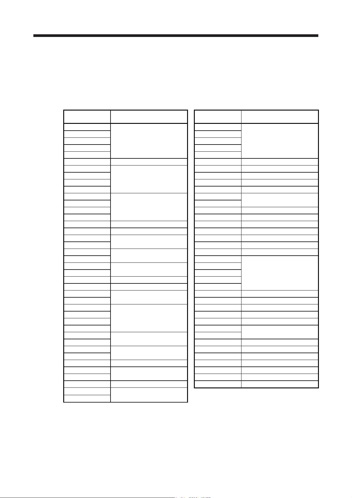
10.3.2 Permissible load to motor inertia when the dynamic brake is used
Use the dynamic brake under the load to motor inertia ratio indicated in the following table. If the load inertia
moment is higher than this value, the dynamic brake may burn. If the load to motor inertia ratio exceeds the
indicated value, contact your local sales office.
The values of the permissible load to motor inertia ratio in the table are the values at the maximum rotation
speed of the servo motor. The value in the parenthesis shows the value at the rated speed.
Servo motor
Permissible load to motor inertia
ratio [multiplier]
Servo motor
Permissible load to motor inertia
ratio [multiplier]
HG-KR053 HG-JR53
HG-KR13 HG-JR73
HG-KR23 30 HG-JR103 30
HG-KR43 HG-JR153
HG-KR73 HG-JR203
HG-MR053 35 HG-JR353 16 (30)
HG-MR13 HG-JR503 15 (30)
HG-MR23
32
HG-JR703 11 (30)
HG-MR43 HG-JR903 18 (30)
HG-MR73 HG-JR701M 5
HG-SR51
30
HG-JR11K1M
10 (30)
HG-SR81 HG-JR15K1M
HG-SR121 HG-JR22K1M 20 (30)
HG-SR201 HG-JR601 5
HG-SR301 16 HG-JR801 30
HG-SR421 15 HG-JR12K1 20 (30)
HG-SR52
30
HG-JR15K1 17 (30)
HG-SR102 HG-JR20K1 26 (30)
HG-SR152
21
HG-JR25K1 21 (30)
HG-SR202 HG-JR534
HG-SR352
13 (15)
HG-JR734
HG-SR502 HG-JR1034 30 (30)
HG-SR702 5 (15) HG-JR1534
HG-SR524 5 (15) HG-JR2034
HG-SR1024
5 (17)
HG-JR3534 20 (30) (Note)
HG-SR1524 HG-JR5034 15 (30)
HG-SR2024
5 (15)
HG-JR7034 11 (30)
HG-SR3524 HG-JR9034 18 (30)
HG-SR5024 HG-JR701M4 7 (10)
HG-SR7024 HG-JR11K1M4
10 (30)
HG-UR72
30
HG-JR15K1M4
HG-UR152 HG-JR22K1M4 20 (30)
HG-UR202
16
HG-JR6014 10
HG-UR352 HG-JR8014 30
HG-UR502 15 HG-JR12K14 20 (30)
HG-RR103
30
HG-JR15K14 30 (30)
HG-RR153 HG-JR20K14 26 (30)
HG-RR203 16 HG-JR25K14 21 (30)
HG-RR353
15
HG-RR503
Note. When the maximum torque is increased to 400%, the permissible load to motor inertia ratio at the maximum speed
of the servo motor is 25 times.
10. CHARACTERISTICS
10 - 13
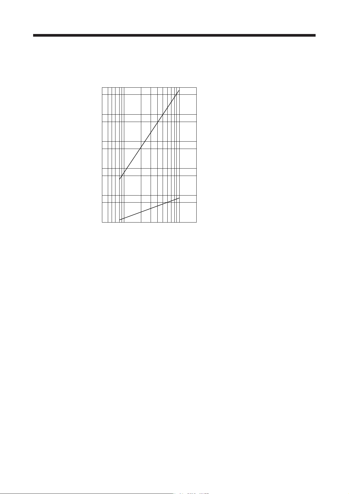
10.4 Cable bending life
The bending life of the cables is shown below. This graph calculated values. Since they are not guaranteed
values, provide a little allowance for these values.
a: Long bending life encoder cable
Long bending life motor power cable
Long bending life electromagnetic brake cable
SSCNET III cable using long distance cable
b: Standard encoder cable
Standard motor power cable
Standard electromagnetic brake cable
SSCNET III cable using inside panel standard cord
SSCNET III cable using outside panel standard cable
Number of bending times [time]
1 × 10
8
5 × 10
7
1 × 10
7
5 × 10
6
1 × 10
6
5 × 10
5
1 × 10
5
5 × 10
4
1 × 10
4
5 × 10
3
1 × 10
3
Bend radius [mm]
4 7 10 20 40 70 100 200
b
a