sh030106u.pdf - 第231页
7. SPEC IAL ADJUSTMEN T FUNCT IONS 7 - 2 7.1.1 Mach ine res onanc e suppres sion fi lter POINT The mac hine res onance s uppres sion fi lter is a d elay f ac tor for the servo system. Therefore, vibrat ion may incr ease …
7. SPECIAL ADJUSTMENT FUNCTIONS
7 - 1
7. SPECIAL ADJUSTMENT FUNCTIONS
POINT
The functions given in this chapter need not be used normally. Use them if you
are not satisfied with the machine status after making adjustment in the methods
in chapter 6.
When you use a linear servo motor, replace the following words in the left to the
words in the right.
Load to motor inertia ratio → Load to motor mass ratio
Torque → Thrust
(Servo motor) speed → (Linear servo motor) speed
7.1 Filter setting
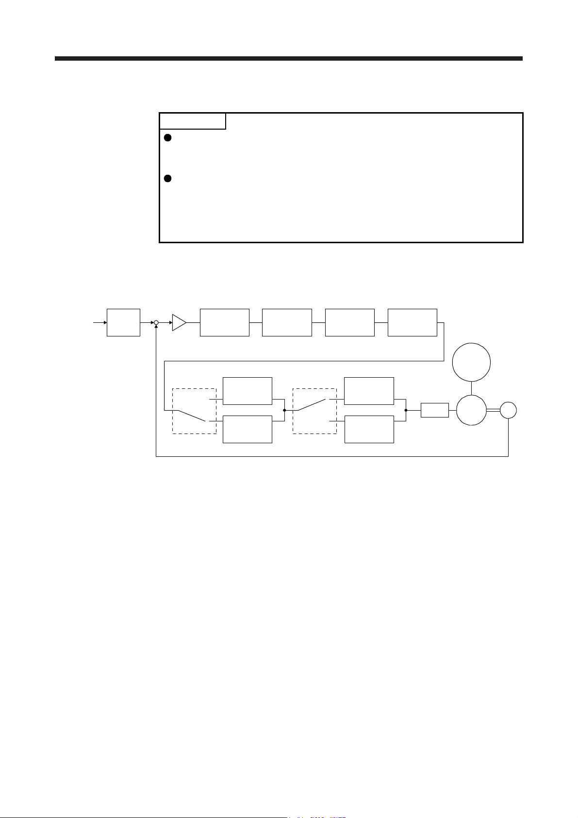
The following filters are available with MR-J4 servo amplifiers.
Command
pulse train
Command
filter
Low-pass
filter
setting
Encoder
Servo motor
PWM
M
Load
[Pr. PB18]
+
-
Machine
resonance
suppression
filter 1
[Pr. PB13] [Pr. PB15] [Pr. PB46]
Machine
resonance
suppression
filter 2
Machine
resonance
suppression
filter 3
Machine
resonance
suppression
filter 4
Machine
resonance
suppression
filter 5
Shaft
resonance
suppression
filter
Robust filter
[Pr. PB48]
[Pr. PB50]
[Pr. PB17]
Speed
control
[Pr. PB49] [Pr. PE41]
7. SPECIAL ADJUSTMENT FUNCTIONS
7 - 2
7.1.1 Machine resonance suppression filter
POINT
The machine resonance suppression filter is a delay factor for the servo system.
Therefore, vibration may increase if you set an incorrect resonance frequency or
set notch characteristics too deep or too wide.
If the frequency of machine resonance is unknown, decrease the notch
frequency from higher to lower ones in order. The optimum notch frequency is
set at the point where vibration is minimal.
A deeper notch has a higher effect on machine resonance suppression but
increases a phase delay and may increase vibration.
A wider notch has a higher effect on machine resonance suppression but
increases a phase delay and may increase vibration.
The machine characteristic can be grasped beforehand by the machine analyzer
on MR Configurator2. This allows the required notch frequency and notch
characteristics to be determined.
If a mechanical system has a unique resonance point, increasing the servo system response level may
cause resonance (vibration or unusual noise) in the mechanical system at that resonance frequency. Using
the machine resonance suppression filter and adaptive tuning can suppress the resonance of the mechanical
system. The setting range is 10 Hz to 4500 Hz.
7. SPECIAL ADJUSTMENT FUNCTIONS
7 - 3
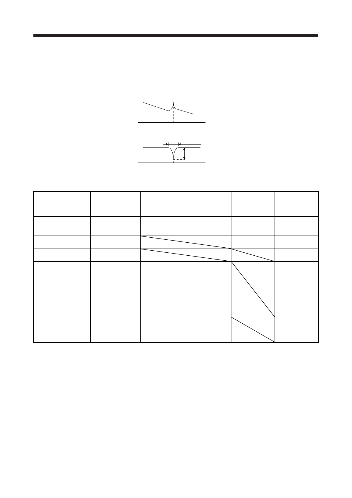
(1) Function
The machine resonance suppression filter is a filter function (notch filter) which decreases the gain of the
specific frequency to suppress the resonance of the mechanical system. You can set the gain
decreasing frequency (notch frequency), gain decreasing depth and width.
Response of
mechanical system
Notch
characteristics
Machine resonance point
Notch frequency
Frequency
Frequency
Notch width
Notch depth
You can set five machine resonance suppression filters at most.
Filter Setting parameter Precaution
Parameter that is
reset with vibration
tough drive
function
Parameter
automatically
adjusted with one-
touch tuning
Machine resonance
suppression filter 1
PB01/PB13/PB14
The filter can be set automatically with
"Filter tuning mode selection" in [Pr.
PB01].
PB13 PB01/PB13/PB14
Machine resonance
suppression filter 2
PB15/PB16 PB15 PB15/PB16
Machine resonance
suppression filter 3
PB46/PB47 PB46/PB47
Machine resonance
suppression filter 4
PB48/PB49
Enabling the machine resonance
suppression filter 4 disables the shaft
resonance suppression filter.
Using the shaft resonance suppression
filter is recommended because it is
adjusted properly depending on the
usage situation.
The shaft resonance suppression filter is
enabled for the initial setting.
PB48/PB49
Machine resonance
suppression filter 5
PB50/PB51
Enabling the robust filter disables the
machine resonance suppression filter 5.
The robust filter is disabled for the initial
setting.
PB51