sh030106u.pdf - 第637页
APPENDIX App. - 6 App. 5.3 Cau tions The followi ng bas ic safety notes mus t be read carefu lly and f ul ly in order t o preve nt injur y to persons or damage to pr operty . Only qu alified p ersonne l are aut horize d …

APPENDIX
App. - 5
App. 5 MR-J3-D05 Safety logic unit
App. 5.1 Contents of the package
Open packing, and confirm the content of packing.
Contents Quantity
MR-J3-D05 Safety logic unit 1
Connector for CN9 1-1871940-4 (TE Connectivity) 1
Connector for CN10 1-1871940-8 (TE Connectivity) 1
MR-J3-D05 Safety Logic Unit Installation Guide 1
App. 5.2 Terms related to safety
App. 5.2.1 Stop function for IEC/EN 61800-5-2
(1) STO function (Refer to IEC/EN 61800-5-2:2016 4.2.2.2 STO.)
This function is integrated into the MR-J4 series servo amplifiers.
The STO function shuts down energy to servo motors, thus removing torque. This function electronically
cuts off power supply in servo amplifiers for MR-J4 series servo amplifiers.
The purpose of this function is as follows.
1) Uncontrolled stop according to stop category 0 of IEC/EN 60204-1
2) Preventing unexpected start-up
(2) SS1 function (Refer to IEC/EN 61800-5-2:2016 4.2.2.3C Safe stop 1 temporal delay.)
SS1 is a function which initiates the STO function when the previously set delay time has passed after
the servo motor starts decelerating. The delay time can be set with MR-J3-D05.
The purpose of this function is as follows. This function is available by using an MR-J4 series servo
amplifier with MR-J3-D05.
Controlled stop according to stop category 1 of IEC/EN 60204-1
App. 5.2.2 Emergency operation for IEC/EN 60204-1
(1) Emergency stop (Refer to IEC/EN 60204-1:2016 9.2.5.4.2 Emergency Stop.)
Emergency stop must override all other functions and actuation in all operation modes. Power to the
machine driving part which may cause a hazardous state must be either removed immediately (stop
category 0) or must be controlled to stop such hazardous state as soon as possible (stop category 1).
Restart must not be allowed even after the cause of the emergency state has been removed.
(2) Emergency shut-off (Refer to IEC/EN 60204-1:2016 9.2.5.4.3 Emergency Switching OFF.)
Removal of input power to driving device to remove electrical risk and to meet above mentioned safety
standards.
APPENDIX
App. - 6
App. 5.3 Cautions
The following basic safety notes must be read carefully and fully in order to prevent injury to persons or
damage to property.
Only qualified personnel are authorized to install, start-up, repair or service the machines in which these
components are installed.
They must be familiar with all applicable local regulations and laws in which machines with these
components are installed, particularly the standards mentioned in this user's manual and the requirements
described in ISO/EN ISO 13849-1:2015, EN IEC 62061, EN 61508, IEC/EN 61800-5-2, and IEC/EN 60204-
1.
The staff responsible for this work must be given express permission from the company to perform start-up,
programming, configuration, and maintenance of the machine in accordance with the safety standards.
WARNING
Improper installation of the safety related components or systems may cause
improper operation in which safety is not assured, and may result in severe
injuries or even death.
Protective Measures
As described in IEC/EN 61800-5-2, the Safe Torque Off (STO) function only prevents the servo amplifier
from supplying energy to the servo motor. Therefore, if an external force acts upon the drive axis,
additional safety measures, such as brakes or counter-weights must be used.
App. 5.4 Residual risk
Machine manufacturers are responsible for all risk evaluations and all associated residual risks. Below are
residual risks associated with the STO/EMG function. Mitsubishi Electric is not liable for any damages or
injuries caused by the residual risks.
(1) The SS1 function only guarantees the delay time before STO/EMG is engaged. Proper setting of this
delay time is the full responsibility of the company and/or individuals responsible for installation and
commissioning of the safety related system. The system, as a whole, must pass safety standards
certification.
(2) When the SS1 delay time is shorter than the required servo motor deceleration time, if the forced stop
function is malfunctioning, or if STO/EMG is engaged while the servo motor is still rotating; the servo
motor will stop with the dynamic brake or freewheeling.
(3) For proper installation, wiring, and adjustment, thoroughly read the installation guide of each individual
safety related component.
(4) Be sure that all safety related switches, relays, sensors, etc., meet the required safety standards.
A Certification Body has confirmed that the Mitsubishi Electric safety-related components mentioned in
this manual meet ISO/EN ISO 13849-1:2015 Category 3, PL d, EN IEC 62061, and EN 61508 SIL 2.
(5) Safety is not assured until safety-related components of the system are completely installed or adjusted.
(6) When replacing a servo amplifier etc. or MR-J3-D05, confirm that the new equipment is exactly the same
as those being replaced. Once installed, be sure to verify the performance of the functions before
commissioning the system.
APPENDIX
App. - 7
(7) Perform all risk assessments and safety level certification to the machine or the system as a whole.
It is recommended that a Certification Body final safety certification of the system be used.
(8) To prevent accumulation of multiple malfunctions, perform a malfunction check at regular intervals as
deemed necessary by the applicable safety standard. Regardless of the system safety level, malfunction
checks should be performed at least once per year.
(9) If the upper and lower power modules in the servo amplifier are shorted and damaged simultaneously,
the servo motor may make a half revolution at a maximum. For a linear servo motor, the primary side will
move a distance of pole pitch.
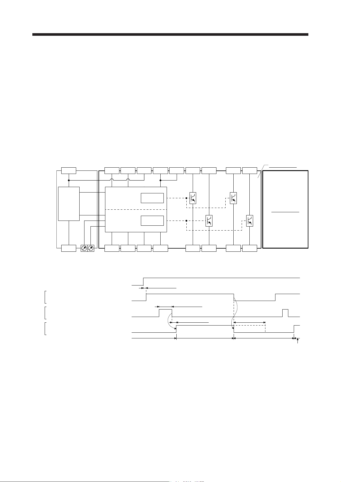
App. 5.5 Block diagram and timing chart
(1) Function block diagram
SDI1A- SDI2A- SDI1B- SDI2B- STO1A- STO2A- SDO1A- SDO2A-
SRESA+ SRESA- TOF1A TOF2A STO1A+ STO2A+ SDO1A+ SDO2A+TOFA
0V
+24V
DCDC
power
Safety logic
TIMER1
TIMER2
A
-axis circui
t
SW1 SW2
B-axis circuit
(2) Operation sequence
A-axis shutdown 1 and 2
B-axis shutdown 1 and 2
Energizing (close)
Shut-off (open)
Release (close)
Normal (open)
Normal (close)
Shut-off (open)
A-axis EMG start/reset
B-axis EMG start/reset
A-axis STO state 1 and 2
B-axis STO state 1 and 2
10 ms or shorter Shut off delay (SW1 and SW2) (Note)
STO status
Control enabled
STO status
50 ms or longer
SDI
SRES
STO
15 ms or longer
Power supply
Control enabled
Note. Refer to App. 5.10.
App. 5.6 Maintenance and disposal
MR-J3-D05 is equipped with LED displays to check errors for maintenance.
Please dispose this unit according to your local laws and regulations.