sh030106u.pdf - 第430页
11. OPT I ONS AND PER IPH ERA L EQU IPM ENT 11 - 10 9 4) Whe n both the main c ircuit power sup ply a nd the co ntr ol circui t power s upply ar e t urned off ON OFF ON OFF ON OFF 0 r/min OFF ON ON OFF 10 ms Coasting Dyn…
11. OPTIONS AND PERIPHERAL EQUIPMENT
11 - 108
3) Alar
m occurrence
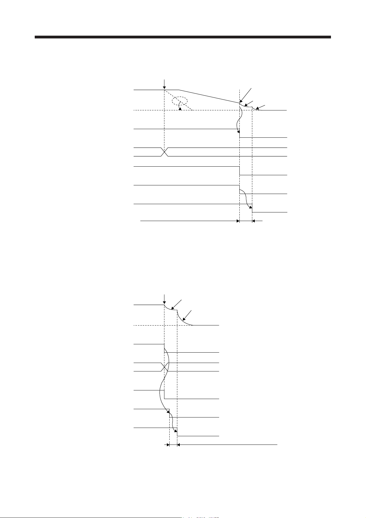
a) When the forced stop deceleration function is enabled
ON
OFF
0 r/min
ON
OFF
DB (Dynamic
brake interlock) (Note 2)
Alarm occurrence
Servo motor speed
Commands from the controller
are not accepted.
Base circuit
(Energy supply to
the servo motor)
Servo amplifier display No alarm Alarm No.
ALM
(Malfunction)
ON (no alarm)
OFF (alarm)
Release
Activate
Dynamic brake
Dynamic brake
Coasting
Release delay time and external relay, etc. (Note 3)
Model speed command 0 and equal
to or less than zero speed (Note 1)
Note 1. The model speed command is a speed command generated in the servo amplifier for forced stop deceleration of the servo
motor.
2. ON: Dynamic brake is not activated
OFF: D
y
namic brake is activated
3. There is delay caused by the magnetic contactor built into the external dynamic brake (about 50 ms) and delay caused by the
external rela
y
.
b) Whe
n the forced stop deceleration function is disabled
OFF
ON
0 r/min
ON
OFF
Coasting
Dynamic brake
Release delay time and external relay, etc. (Note 2)
DB (Dynamic
brake interlock) (Note 1)
Alarm occurrence
Servo amplifier display
ALM
(Malfunction)
Dynamic brake
ON (no alarm)
OFF (alarm)
Release
Activate
Base circuit
(Energy supply to
the servo motor)
Servo motor speed
No alarm Alarm No.
Note 1. ON: Dynamic brake is not activated
OFF: D
y
namic brake is activated
2. There is delay caused by the magnetic contactor built into the external dynamic brake (about 50 ms) and delay caused by the
external rela
y
.
11. OPTIONS AND PERIPHERAL EQUIPMENT
11 - 109
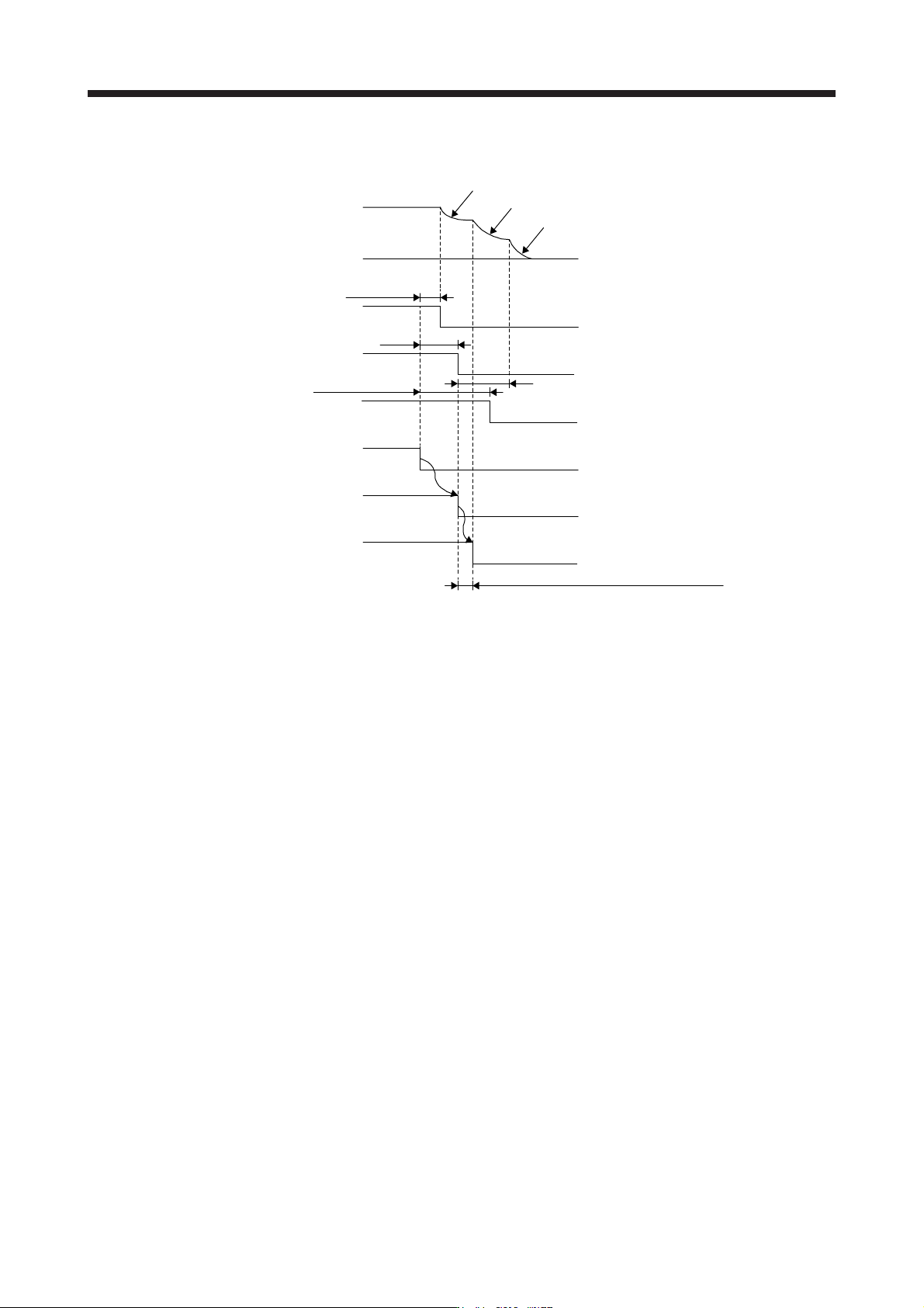
4) Whe
n both the main circuit power supply and the control circuit power supply are turned off
ON
OFF
ON
OFF
ON
OFF
0 r/min
OFF
ON
ON
OFF
10 ms
Coasting
Dynamic brake
DB (Dynamic
brake interlock) (Note 4)
MBR (Electromagnetic
brake interlock) (Note 3)
Dynamic brake
Release
Activate
Base circuit
Servo motor speed
Electromagnetic brake interlock
ALM
(Malfunction)
OFF (Valid)
Power
Main circuit
Control circuit
Release delay time and external relay, etc. (Note 5)
15 to 60 ms (Note 2) Electromagnetic brake
operation delay time
7 ms (Note 1)
Note 1. When the power is off, DB (dynamic brake interlock) will turn off. Before an output short-circuit occurs, the base circuit turns off
faster than normal cases.
(
Onl
y
when DB is assi
g
ned as an output si
g
nal
)
2. The len
g
th of time varies dependin
g
on the operation status.
3. ON: Electromagnetic brake is not activated
OFF: Electroma
g
netic brake is activated
4. ON: Dynamic brake is not activated
OFF: D
y
namic brake is activated
5. There is delay caused by the magnetic contactor built into the external dynamic brake (about 50 ms) and delay caused by the
external rela
y
.
11. OPTIONS AND PERIPHERAL EQUIPMENT
11 - 110
(b) Whe
n the forced stop deceleration function is not used
1) Ready-off command from controller
For information on the ready-off command from controller, refer to section 11.17 (3)
(a) 1).
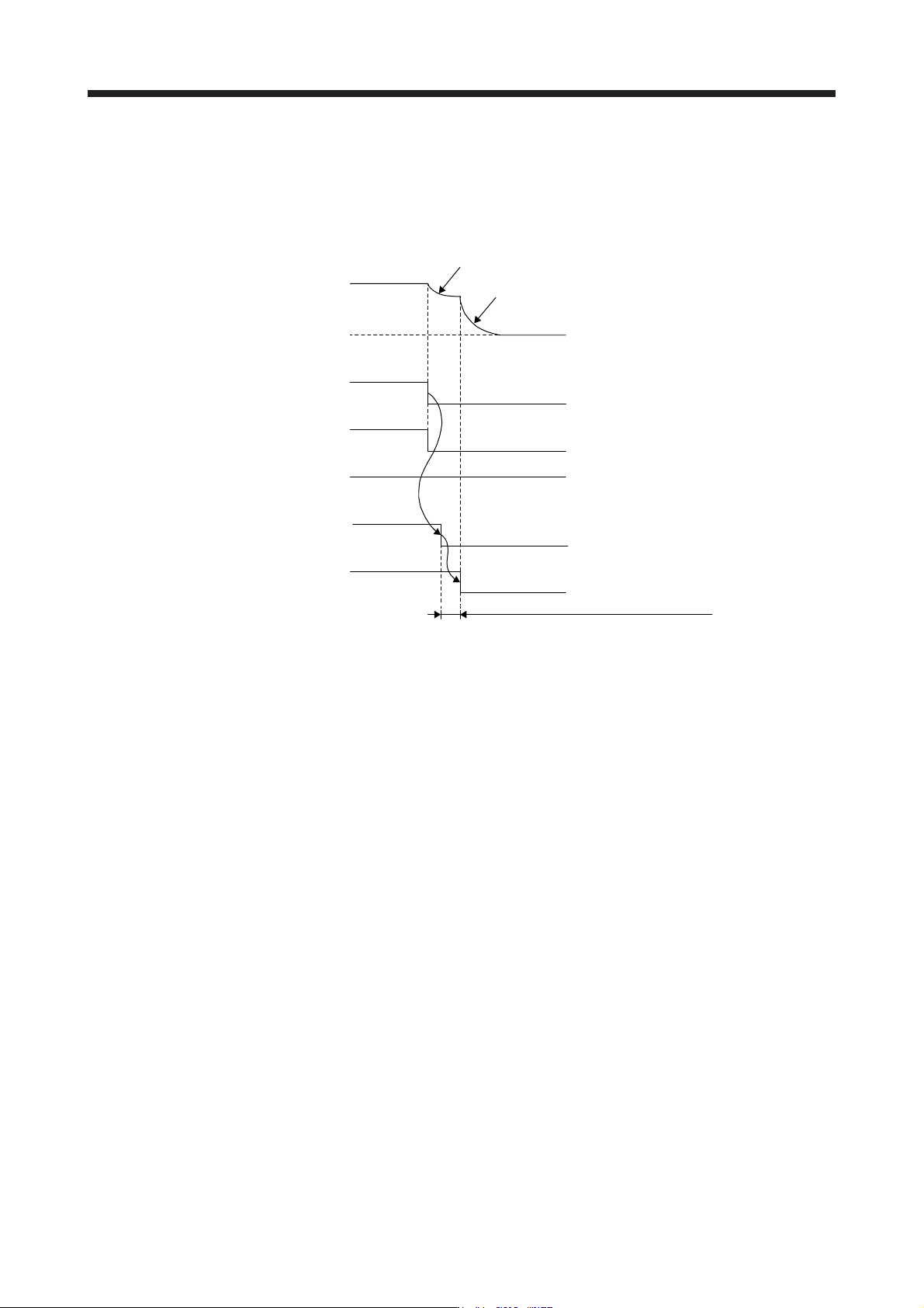
2) Turning the forced stop command (from controller) or EM1 (Forced stop 1) off
ON
OFF
0 r/min
ON
OFF
Coasting
Dynamic brake
Servo motor speed
Release
Activate
DB (Dynamic
brake interlock) (Note 1)
Dynamic brake
Emergency stop command
(from controller) or EM1
(Forced stop 1)
Base circuit
(Energy supply to
the servo motor)
Disabled (ON)
Enabled (OFF)
ON (no alarm)
OFF (alarm)
ALM
(Malfunction)
Release delay time and external relay, etc. (Note 2)
Note 1. ON: Dynamic brake is not activated
OFF: D
y
namic brake is activated
2. There is delay caused by the magnetic contactor built into the external dynamic brake (about 50 ms) and delay caused by the
external rela
y
.
3) Alarm oc
currence
For information on the alarm occurrence, refer to section 11.17 (3) (a) 3) b).
4)
When both the main circuit power supply and the control circuit power supply are turned off
For information on when both the main circuit power supply and the control circuit power supply
are turned off, refer to section 11.17 (3) (a) 4).