sh030106u.pdf - 第186页
5. PARAMETE RS 5 - 41 No. Sym bol Name and function Initial value [unit] Setting range PC27 **COP9 Functi on selection C-9 This is us ed to select a polarity of the l inear encoder or load -si de encoder. Refer to t he &…
5. PARAMETERS
5 - 40
No. Symbol Name and function
Initial
value
[unit]
Setting
range
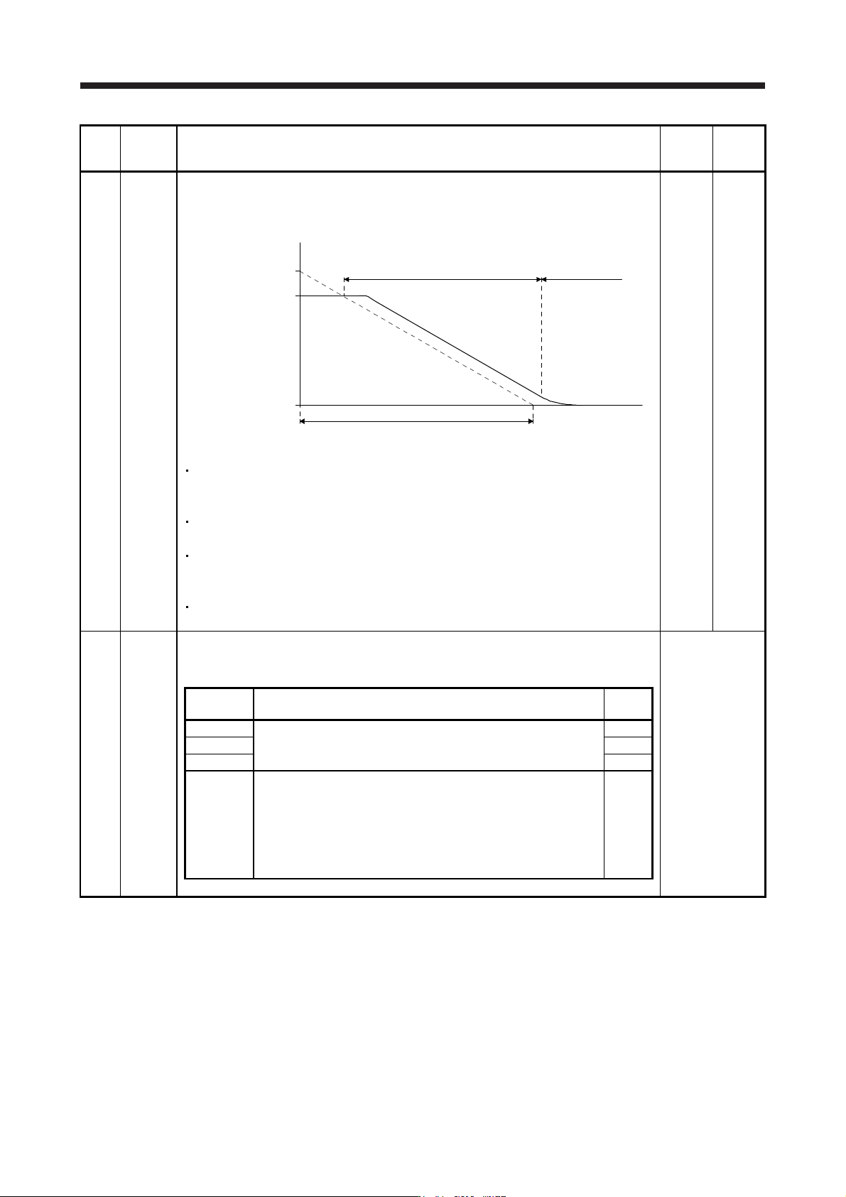
PC24 RSBR Forced stop deceleration time constant
This is used to set deceleration time constant when you use the forced stop deceleration
function.
Set the time per ms from the rated speed to 0 r/min or 0 mm/s. Setting "0" will be 100 ms.
Forced stop deceleration
[Pr. PC24]
0 r/min
(0 mm/s)
Servo motor speed
Rated speed
Dynamic brake
deceleration
(Linear servo motor
speed)
[Precautions]
If the servo motor torque or linear servo motor thrust is saturated at the maximum torque
during forced stop deceleration because the set time is too short, the time to stop will be
longer than the set time constant.
[AL. 50 Overload alarm 1] or [AL. 51 Overload alarm 2] may occur during forced stop
deceleration, depending on the set value.
After an alarm that leads to a forced stop deceleration, if an alarm that does not lead to a
forced stop deceleration occurs or if the control circuit power supply is cut, dynamic braking
will start regardless of the deceleration time constant setting.
Set a longer time than deceleration time at quick stop of the controller. If a shorter time is
set, [AL. 52 Error excessive] ma
y
occur.
100
[ms]
0 to
20000
PC26 **COP8 Function selection C-8
Used to select the communication method of the encoder cable to be connected to the CN2L
connector of MR-J4-_B_-RJ.
Refer to the
"Name and
function" column.
Setting
digit
Explanation
Initial
value
_ _ _ x For manufacturer setting 0h
_ _ x _ 0h
_ x _ _ 0h
x _ _ _ Load-side encoder communication method
0: Two-wire type
1: Four-wire type
When using a load-side encoder of A/B/Z-phase differential output
method, set "0".
Setting "1" by using a servo amplifier other than MR-J4-_B_-RJ will
trigger [AL. 37].
0h
5. PARAMETERS
5 - 41
No. Symbol Name and function
Initial
value
[unit]
Setting
range
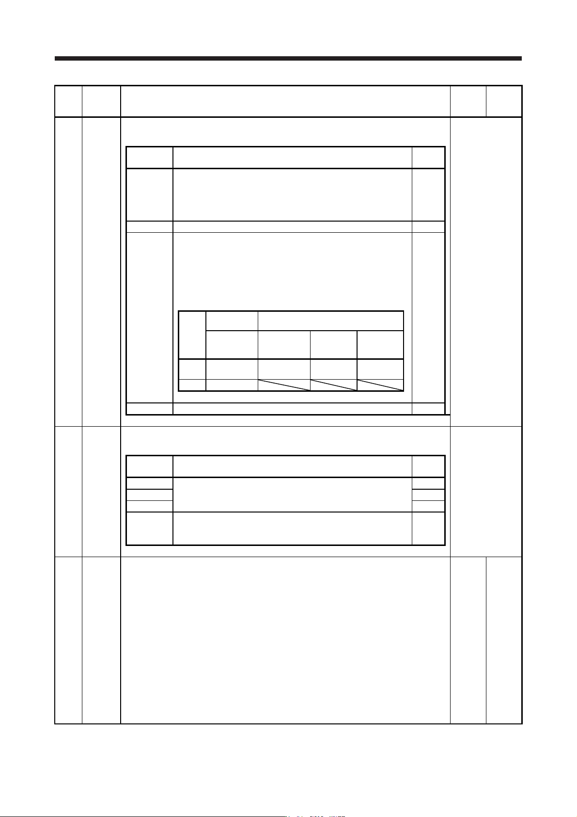
PC27 **COP9 Function selection C-9
This is used to select a polarity of the linear encoder or load-side encoder.
Refer to the
"Name and
function" column.
Setting
digit
Explanation
Initial
value
_ _ _ x Encoder pulse count polarity selection
0: Encoder pulse increasing direction in the servo motor CCW or
positive direction
1: Encoder pulse decreasing direction in the servo motor CCW or
positive direction
0h
_ _ x _ For manufacturer setting 0h
_ x _ _
Selection of A/B/Z-phase input interface encoder Z-phase
connection judgment function
This is used to select a non-signal detection of A/B/Z-phase input
interface encoder pulse train signal used as linear encoder or load-
side encoder.
This digit is enabled only when you use an A/B/Z-phase input
interface encoder.
0h
Setting
value
Detection of
disconnection
Alarm status
Z-phase-side
non-signal
Standard (scale
measurement
enabled)
Fully closed
loop system
Linear servo
system
0 Enabled
[AL. 71.6]
(Z-phase)
[AL. 71.6]
(Z-phase)
[AL. 20.6]
(Z-phase)
1 Disabled
x _ _ _ For manufacturer setting 0h
PC29 *COPB Function selection C-B
This is used to select the POL reflection at torque control.
Refer to the
"Name and
function" column.
Setting
digit
Explanation
Initial
value
_ _ _ x For manufacturer setting 0h
_ _ x _ 0h
_ x _ _ 0h
x _ _ _ POL reflection selection at torque control
0: Enabled
1: Disabled
0h
PC31 RSUP1 Vertical axis freefall prevention compensation amount
Set the compensation amount of the vertical axis freefall prevention function.
Set it per servo motor rotation amount or linear servo motor travel distance.
When a positive value is set, compensation is performed to the address increasing direction.
When a negative value is set, compensation is performed to the address decreasing direction.
The vertical axis freefall prevention function is performed when all of the following conditions
are met.
1) Position control mode
2) The value of the parameter is other than "0".
3) "Forced stop deceleration function selection" of [Pr. PA04] is set to "Forced stop
deceleration function enabled (2 _ _ _ )".
4) EM2 (forced stop 2) is off, an alarm occurred, or SSCNET III/H communication shut off
when the servo motor speed is the zero speed or less.
5) MBR (Electromagnetic brake interlock) was enabled in [Pr. PD07] to [Pr. PD09], and the
base circuit shut-off dela
y
time was set in [Pr. PC02].
0
[0.0001
rev]/
[0.01 mm]
-25000
to
25000
5. PARAMETERS
5 - 42
No. Symbol Name and function
Initial
value
[unit]
Setting
range
PC38 ERW Error excessive warning level
Set an error excessive warning level.
To enable the parameter, select "Enabled (1 _ _ _)" of "[AL. 9B Error excessive warning]
selection" in [Pr. PC05].
You can change the setting unit with "Error excessive alarm/error excessive warning level unit
selection" in [Pr. PC06].
Set this per rev. for rotary servo motors and direct drive motors. Setting "0" will be "1 rev", and
setting over 200 rev will be clamped with 200 rev. Set this per mm for linear servo motors.
Setting "0" will be 50 mm.
When an error reaches the set value, [AL. 9B Error excessive warning] will occur. When the
error decreases lower than the set value, the warning will be canceled automatically. The
minimum pulse width of the warning signal is 100 [ms].
Set as follows.: [Pr. PC38 Error excessive warning level] < [Pr. PC01 Error excessive alarm
level] When you set as follows, [AL. 52 Error excessive] will occur earlier than the warning.:
[Pr. PC38 Error excessive warning level] ≥ [Pr. PC01 Error excessive alarm level]
This parameter is used by servo amplifier with software version B4 or later.
0
[rev]/
[mm]
0
to
1000
5.2.4 I/O setting parameters ([Pr. PD_ _ ])
No. Symbol Name and function
Initial
value
[unit]
Setting
range
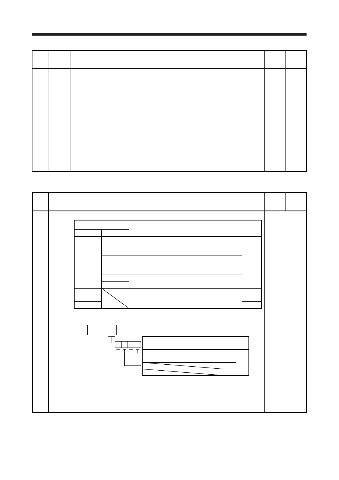
PD02 *DIA2 Input signal automatic on selection 2
Refer to the
"Name and
function" column.
Setting digit
Explanation
Initial
value
HEX. BIN.
_ _ _ x _ _ _ x FLS (Upper stroke limit) selection
0: Disabled
1: Enabled
0h
_ _ x _ RLS (Lower stroke limit) selection
0: Disabled
1: Enabled
_ x _ _ For manufacturer setting
x _ _ _
_ _ x _ For manufacturer setting 0h
_ x _ _ 0h
x _ _ _ 0h
Convert the setting value into hexadecimal as follows.
0
BIN 0: Use for an external input signal.
BIN 1: Automatic on
Initial value
BIN HEX
Signal name
0
0
000
0
0
FLS (Upper stroke limit) selection
RLS (Lower stroke limit) selection
When performing a magnetic pole detection without using FLS (Upper stroke limit) and RLS
(Lower stroke limit), you can disable FLS and RLS by setting [Pr. PL08 Linear servo motor/DD
motor function selection 3] to "_ 1 _ _".