sh030106u.pdf - 第573页
17. APPLICATIO N OF FUNCTIONS 17 - 22 No. Sym bol Name and function Initial value [unit] Setting range PX23 *XOP3 Functi on selection X-3 Refer to the "Name and function" c olumn. Setting digit Explanation Init…
17. APPLICATION OF FUNCTIONS
17 - 21
No. Symbol Name and function
Initial
value
[unit]
Setting
range
PX20 NHQ4 Notch shape selection 4
Set the shape of the machine resonance suppression filter 4.
Refer to the
"Name and
function" column.
Setting
digit
Explanation
Initial
value
_ _ _ x Machine resonance suppression filter 4 selection
0: Disabled
1: Enabled
When you select "Enabled" of this digit, [Pr. PB17 Shaft resonance
suppression filter] is not available.
0h
_ _ x _ Notch depth selection
0: -40 dB
1: -14 dB
2: -8 dB
3: -4 dB
0h
_ x _ _ Notch width selection
0: α = 2
1: α = 3
2: α = 4
3: α = 5
0h
x _ _ _ For manufacturer setting 0h
PX21 NH5 Machine resonance suppression filter 5
Set the notch frequency of the machine resonance suppression filter 5.
To enable the setting value, select "Enabled (_ _ _ 1)" of "Machine resonance suppression
filter 5 selection" in [Pr. PX22].
4500
[Hz]
10
to
4500
PX22 NHQ5 Notch shape selection 5
Set the shape of the machine resonance suppression filter 5.
When you select "Enabled (_ _ _ 1)" of "Robust filter selection" in [Pr. PX31], the machine
resonance suppression filter 5 is not available.
Refer to the
"Name and
function" column.
Setting
digit
Explanation
Initial
value
_ _ _ x Machine resonance suppression filter 5 selection
0: Disabled
1: Enabled
0h
_ _ x _ Notch depth selection
0: -40 dB
1: -14 dB
2: -8 dB
3: -4 dB
0h
_ x _ _ Notch width selection
0: α = 2
1: α = 3
2: α = 4
3: α = 5
0h
x _ _ _ For manufacturer setting 0h
17. APPLICATION OF FUNCTIONS
17 - 22
No. Symbol Name and function
Initial
value
[unit]
Setting
range
PX23 *XOP3 Function selection X-3
Refer to the
"Name and
function" column.
Setting
digit
Explanation
Initial
value
_ _ _ x
Torque limit function selection at instantaneous power failure
(instantaneous power failure tough drive selection)
0: Disabled
1: Enabled
When an instantaneous power failure occurs during operation, you
can save electric energy charged in the capacitor in the servo
amplifier by limiting torque at acceleration. You can also delay the
time until [AL. 10.2 Voltage drop in the main circuit power] occurs
with instantaneous power failure tough drive function. Doing this will
enable you to set a longer time in [Pr. PX28 SEMI-F47 function -
Instantaneous power failure detection time].
To enable the torque limit function at instantaneous power failure,
select "Enabled (_ 1 _ _)" of "SEMI-F47 function selection" in [Pr.
PX25].
This parameter setting is used with servo amplifier with software
version B0 or later.
0h
_ _ x _ For manufacturer setting 0h
_ x _ _ 0h
x _ _ _ 0h
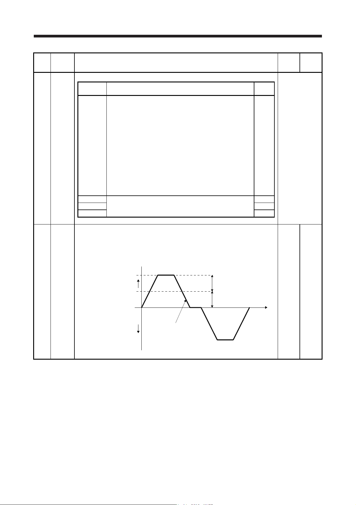
PX24 FRIC Machine diagnosis function - Friction judgment speed
Set a (linear) servo motor speed that divides a friction estimation area into high and low during
the friction estimation process of the machine diagnosis.
Setting "0" will set a value half of the rated speed.
When your operation pattern is under the rated speed, we recommend that you set a half
value of the maximum speed.
Forward rotation
direction
0 r/min
(0 mm/s)
Operation pattern
[Pr. PX24] setting
Maximum speed in operation
Servo motor
speed
Reverse rotation
direction
0
[r/min]/
[mm/s]
0 to
permis-
sible
speed
17. APPLICATION OF FUNCTIONS
17 - 23
No. Symbol Name and function
Initial
value
[unit]
Setting
range
PX25 *TDS Tough drive setting
Alarms may not be avoided with the tough drive function depending on the situations of the
power supply and load fluctuation.
You can assign MTTR (During tough drive) to pins CN3-9, CN3-13, and CN3-15 with [Pr.
PD07] to [Pr. PD09].
Refer to the
"Name and
function" column.
Setting
digit
Explanation
Initial
value
_ _ _ x For manufacturer setting 0h
_ _ x _ Vibration tough drive selection
0: Disabled
1: Enabled
Selecting "1" enables to suppress vibrations by automatically
changing setting values of [Pr. PB13 Machine resonance
suppression filter 1] and [Pr. PB15 Machine resonance suppression
filter 2] in case that the vibration exceeds the value of the oscillation
level set in [Pr. PX26].
Refer to (8) in this section for details.
0h
_ x _ _ SEMI-F47 function selection
0: Disabled
1: Enabled
Selecting "1" enables to avoid triggering [AL. 10 Undervoltage]
using the electrical energy charged in the capacitor in case that an
instantaneous power failure occurs during operation. In [Pr. PX28
SEMI-F47 function - Instantaneous power failure detection time],
set the time until the occurrence of [AL. 10.1 Voltage drop in the
control circuit power].
0h
x _ _ _ For manufacturer setting 0h
PX26 OSCL1 Vibration tough drive - Oscillation detection level
Set a filter readjustment sensitivity of [Pr. PB13 Machine resonance suppression filter 1] and
[Pr. PB15 Machine resonance suppression filter 2] while the vibration tough drive is enabled.
However, setting "0" will be 50%.
Example: When you set "50" to the parameter, the filter will be readjusted at the time of 50%
or more oscillation level.
50
[%]
0
to
100
PX27 *OSCL2 Vibration tough drive function selection
Refer to the
"Name and
function" column.
Setting
digit
Explanation
Initial
value
_ _ _ x Oscillation detection alarm selection
0: [AL. 54 Oscillation detection] will occur at oscillation detection.
1: [AL. F3.1 Oscillation detection warning] will occur at oscillation
detection.
2: Oscillation detection function disabled
Select alarm or warning when an oscillation continues at a filter
readjustment sensitivity level of [Pr. PX26].
The digit is continuously enabled regardless of the vibration tough
drive in [Pr. PX25].
0h
_ _ x _ For manufacturer setting 0h
_ x _ _ 0h
x _ _ _ 0h