sh030106u.pdf - 第613页
17. APPLICATIO N OF FUNCTIONS 17 - 62 b) When the b us volta ge does not dec rease lower than U ndervolt a ge leve l with in the instantan eous power fai lure tim e of the co ntrol c ircuit power s upply The operat ion c…
17. APPLICATION OF FUNCTIONS
17 - 61
2) Instantaneous power failure time of control circuit power supply < [Pr. PX28 SEMI-F47 function -
Instantaneous power failure detection time]
Operation status differs depending on how bus voltage decrease.
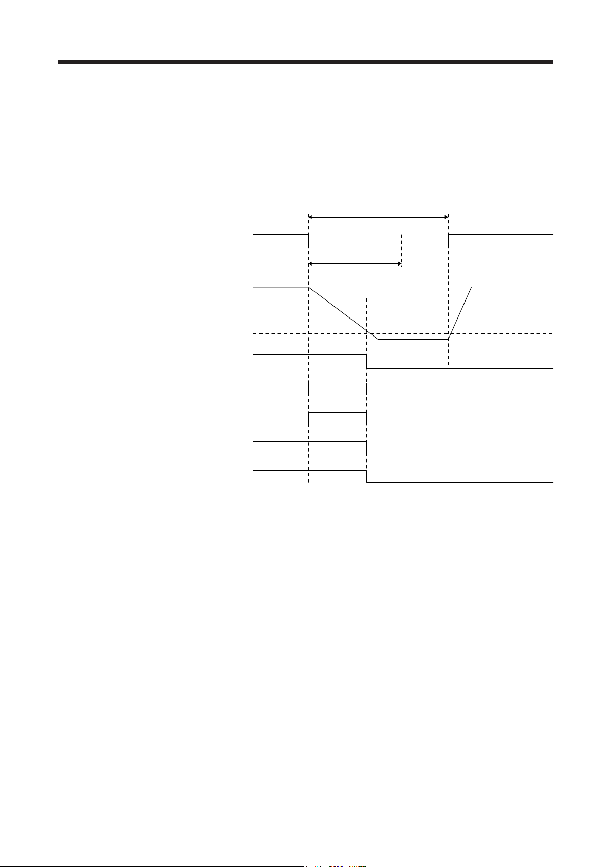
a) When the bus voltage decreases lower than Undervoltage level within the instantaneous
power failure time of the control circuit power supply
[AL. 10 Undervoltage] occurs when the bus voltage decrease lower than Undervoltage level
regardless of the enabled instantaneous power failure tough drive.
[Pr. PX28]
Instantaneous power failure time of the control circuit power supply
ON
OFF
ON
OFF
ON
OFF
ON
OFF
ON
OFF
Bus voltage
Undervoltage level
(Note)
A
LM
(Malfunction)
MTTR
(During tough drive)
MBR
(Electromagnetic
brake interlock)
Base circuit
W
NG
(Warning)
Control circuit
power supply
ON (energization)
OFF (power failure)
Note. Refer to table 17.8 for the undervolta
g
e level.
17. APPLICATION OF FUNCTIONS
17 - 62
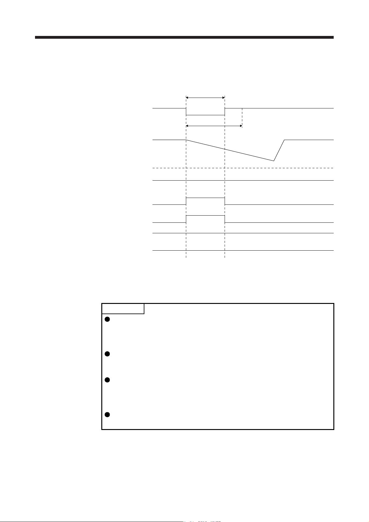
b) When the bus voltage does not decrease lower than Undervoltage level within the
instantaneous power failure time of the control circuit power supply
The operation continues without alarming.
Bus voltage
Undervoltage level
(Note)
A
LM
(Malfunction)
MTTR
(During tough drive)
MBR
(Electromagnetic
brake interlock)
Base circuit
W
NG
(Warning)
[Pr. PX28]
Instantaneous power failure time of the
control circuit power supply
ON
OFF
ON
OFF
ON
OFF
ON
OFF
ON
OFF
Control circuit
power suppl
y
ON (energization)
OFF (power failure)
Note. Refer to table 17.8 for the undervolta
g
e level.
(8) Compliance with SEMI-F47 standard
POINT
The control circuit power supply of the servo amplifier can be possible to comply
with SEMI-F47 standard. However, a back-up capacitor may be necessary for
instantaneous power failure in the main circuit power supply depending on the
power supply impedance and operating situation.
Use a 3-phase for the input power supply of the servo amplifier. Using a 1-phase
100 V AC/200 V AC for the input power supply will not comply with SEMI-F47
standard.
The external dynamic brake cannot be used for compliance with SEMI-F47
standard. Do not assign DB (Dynamic brake interlock) in [Pr. PD07] to [Pr.
PD09]. Failure to do so will cause the servo amplifier to become servo-off when
an instantaneous power failure occurs.
Be sure to perform actual machine tests and detail checks for power supply
instantaneous power failure of SEMI-F47 standard with your equipment.
The following explains the compliance with "SEMI-F47 semiconductor process equipment voltage sag
immunity test" of MR-J4 series.
This function enables to avoid triggering [AL. 10 Undervoltage] using the electrical energy charged in the
capacitor in case that an instantaneous power failure occurs during operation.
17. APPLICATION OF FUNCTIONS
17 - 63
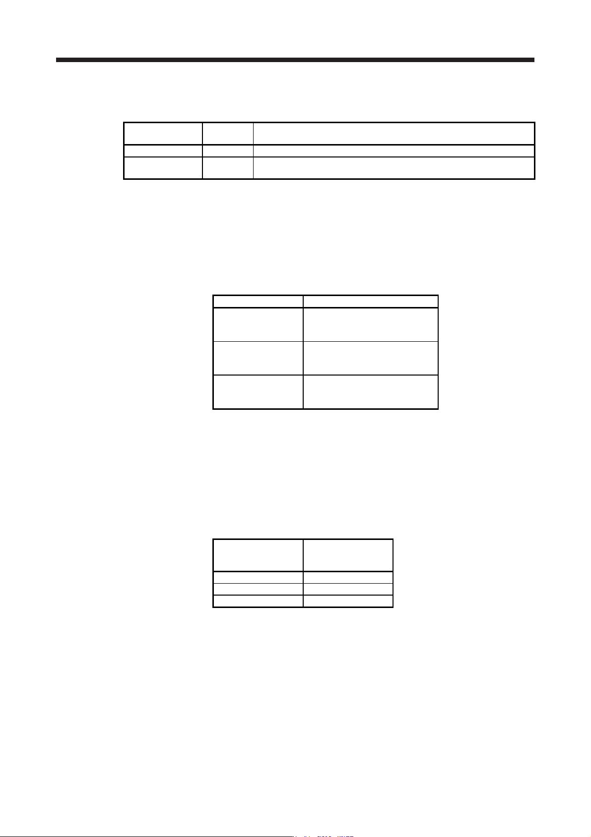
(a) Parameter setting
Setting [Pr. PX25] and [Pr. PX28] as follows will enable SEMI-F47 function.
Parameter
Setting
value
Description
PX25 _ 1 _ _ Enable SEMI-F47 function selection.
PX28 200
Set the time [ms] of the [AL. 10.1 Voltage drop in the control circuit power]
occurrence.
Enabling SEMI-F47 function will change operation as follows.
1) The voltage will drop in the control circuit power with "Rated voltage × 50% or less". 200 ms later,
[AL. 10.1 Voltage drop in the control circuit power] will occur.
2) [AL. 10.2 Voltage drop in the main circuit power] will occur when bus voltage is as follows.
Table 17.8 Voltages which trigger [AL. 10.2 Voltage drop in the main circuit power]
Servo amplifier Bus voltage which triggers alarm
MR-J4-10B(-RJ)
to
MR-J4-700B(-RJ)
158 V DC
MR-J4-11KB(-RJ)
to
MR-J4-22KB(-RJ)
200 V DC
MR-J4-60B4(-RJ)
to
MR-J4-22KB4(-RJ)
380 V DC
3) MBR (Electromagnetic brake interlock) will turn off when [AL. 10.1 Voltage drop in the control
circuit power] occurs.
(b) Requirements conditions of SEMI-F47 standard
Table 17.9 shows the permissible time of instantaneous power failure for instantaneous power failure
of SEMI-F47 standard.
Table 17.9 Requirements conditions of SEMI-F47 standard
Instantaneous power
failure voltage
Permissible time of
instantaneous power
failure [s]
Rated voltage × 80% 1
Rated voltage × 70% 0.5
Rated voltage × 50% 0.2