sh030106u.pdf - 第164页
5. PARAMETE RS 5 - 19 No. Sym bol Name and function Initial value [unit] Setting range PA20 *TDS Tough drive setti ng Alarms may not be avoided wit h the tough drive func tion dependi ng on the situations of the power su…
5. PARAMETERS
5 - 18
No. Symbol Name and function
Initial
value
[unit]
Setting
range
PA17 **MSR 0000h
Refer to
the
"Name
and
function"
column.
Linear servo motor
series
Linear servo motor
(primary side)
Parameter
LM-K2P1A-01M-2SS1 1101h
LM-K2P1C-03M-2SS1 1301h
LM-K2P2A-02M-1SS1 2101h
LM-K2 LM-K2P2C-07M-1SS1 00B8h 2301h
LM-K2P2E-12M-1SS1 2501h
LM-K2P3C-14M-1SS1 3301h
LM-K2P3E-24M-1SS1 3501h
PA18 **MTY Servo motor type setting
When you use a linear servo motor, select its model from [Pr. PA17] and [Pr. PA18]. Set this
and [Pr. PA17] at a time.
Refer to the table of [Pr. PA17] for settings.
0000h
Refer to
the
"Name
and
function"
column
of [Pr.
PA17].
PA19 *BLK Parameter writing inhibit
Select a reference range and writing range of the parameter.
Refer to table 5.3 for settings.
00ABh
Refer to
the
"Name
and
function"
column.
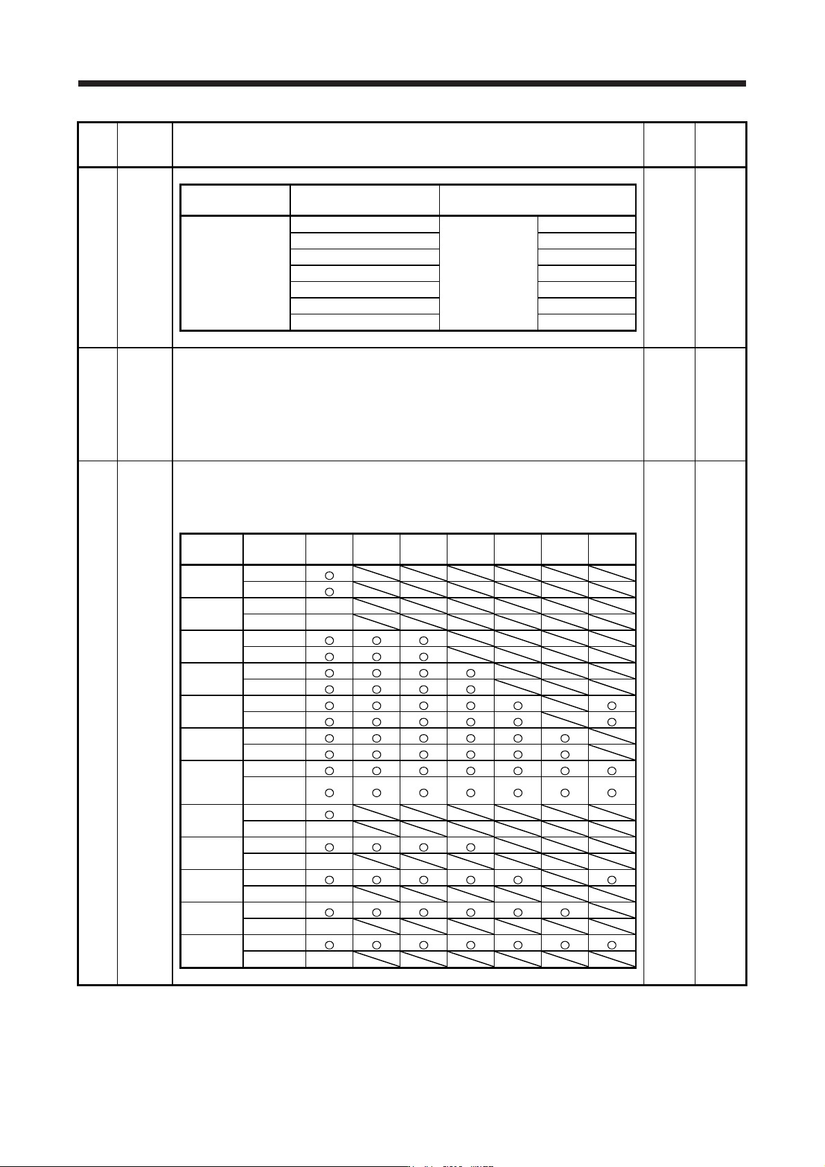
Table 5.3 [Pr. PA19] setting value and reading/writing range
PA19
Setting
operation
PA PB PC PD PE PF PL
Other than
below
Reading
Writing
000Ah
Reading Only 19
Writing Only 19
000Bh
Reading
Writing
000Ch
Reading
Writing
000Fh
Reading
Writing
00AAh
Reading
Writing
00ABh
(initial
value)
Reading
Writing
100Bh
Reading
Writing Only 19
100Ch
Reading
Writing Only 19
100Fh
Reading
Writing Only 19
10AAh
Reading
Writing Only 19
10ABh
Reading
Writing Only 19

5. PARAMETERS
5 - 19
No. Symbol Name and function
Initial
value
[unit]
Setting
range
PA20 *TDS Tough drive setting
Alarms may not be avoided with the tough drive function depending on the situations of the
power supply and load fluctuation.
You can assign MTTR (During tough drive) to pins CN3-9, CN3-13 and CN3-15 with [Pr.
PD07] to [Pr. PD09].
Refer to the
"Name and
function" column.
Setting
digit
Explanation
Initial
value
_ _ _ x For manufacturer setting 0h
_ _ x _ Vibration tough drive selection
0: Disabled
1: Enabled
Selecting "1" enables to suppress vibrations by automatically
changing setting values of [Pr. PB13 Machine resonance
suppression filter 1] and [Pr. PB15 Machine resonance suppression
filter 2] in case that the vibration exceed the value of the oscillation
level set in [Pr. PF23].
Refer to section 7.3 for details.
0h
_ x _ _ SEMI-F47 function selection
0: Disabled
1: Enabled
Selecting "1" enables to avoid occurring [AL. 10 Undervoltage] using
the electrical energy charged in the capacitor in case that an
instantaneous power failure occurs during operation. Set the time of
until [AL. 10.1 Voltage drop in the control circuit power] occurs in [Pr.
PF25 SEMI-F47 function - Instantaneous power failure detection
time].
0h
x _ _ _ For manufacturer setting 0h
PA21 *AOP3 Function selection A-3
Refer to the
"Name and
function" column.
Setting
digit
Explanation
Initial
value
_ _ _ x One-touch tuning function selection
0: Disabled
1: Enabled
When the digit is "0", the one-touch tuning with MR Configurator2
will be disabled.
1h
_ _ x _ For manufacturer setting 0h
_ x _ _ 0h
x _ _ _ 0h

5. PARAMETERS
5 - 20
No. Symbol Name and function
Initial
value
[unit]
Setting
range
PA22 **PCS Position control composition selection
Refer to the
"Name and
function" column.
Setting
digit
Explanation
Initial
value
_ _ _ x For manufacturer setting 0h
_ _ x _ Super trace control selection
0: Disabled
2: Enabled
This parameter setting is used with servo amplifier with software
version B4 or later.
0h
_ x _ _ For manufacturer setting 0h
x _ _ _
Scale measurement function selection
0: Disabled
1: Used in absolute position detection system
2: Used in incremental system
The absolute position detection system cannot be used while an
incremental type encoder is used. Enabling absolute position
detection system will trigger [AL. 37 Parameter error].
Additionally, the setting is enabled only in the standard control
mode. Setting other than "0" in other operation modes triggers [AL.
37 Parameter error].
0h
PA23 DRAT Drive recorder arbitrary alarm trigger setting
Refer to the
"Name and
function" column.
Setting
digit
Explanation
Initial
value
_ _ x x
Alarm detail No. setting
Set the digits when you execute the trigger with arbitrary alarm
detail No. for the drive recorder function.
When these digits are "0 0", only the arbitrary alarm No. setting will
be enabled.
00h
x x _ _
Alarm No. setting
Set the digits when you execute the trigger with arbitrary alarm No.
for the drive recorder function.
When "0 0" are set, arbitrary alarm trigger of the drive recorder will
be disabled.
00h
Setting example:
To activate the drive recorder when [AL. 50 Overload 1] occurs, set "5 0 0 0".
To activate the drive recorder when [AL. 50.3 Thermal overload error 4 during operation]
occurs, set "5 0 0 3".
PA24 AOP4 Function selection A-4
Refer to the
"Name and
function" column.
Setting
digit
Explanation
Initial
value
_ _ _ x
Vibration suppression function selection
0: Standard mode
1: 3 inertia mode
2: Low response mode
When two low resonance frequencies are generated, select "3
inertia mode (_ _ _ 1)". When the load to motor inertia ratio
exceeds the recommended load to motor inertia ratio, select "Low
response mode (_ _ _ 2)".
When you select the standard mode or low response mode,
"Vibration suppression control 2" is not available.
When you select the 3 inertia mode, the feed forward gain is not
available.
Before changing the control mode with the controller during the 3
inertia mode or low response mode, stop the motor.
0h
_ _ x _ For manufacturer setting 0h
_ x _ _ 0h
x _ _ _ 0h