sh030106u.pdf - 第646页
APPENDIX App. - 15 2) Connec ting wires a) C onfirm the m odel n umber of the hous ing, cont act and tool to be us ed. b) Ins ert the too l diagon ally int o the rec eptacle as sembly . c) Insert the tool unti l it hits …
APPENDIX
App. - 14
App. 5.8.3 Wiring CN9 and CN10 connectors
Handle with the tool with care when connecting wires.
(1) Wire strip
(a) Use wires with size of AWG 24 to 20 (0.22 mm
2
to 0.5 mm
2
) (recommended electric wire: UL1007)
and strip the wires to make the stripped length 7.0 mm ± 0.3 mm. Confirm the stripped length with
gauge, etc. before using the wires.
(b) If the stripped wires are bent, loose or too thick due to twisting too much, fix the wires by twisting
lightly, etc. Then, confirm the stripped length before using the wires. Do not use excessively
deformed wires.
(c) Smooth out the wire surface and stripped insulator surface.
(2) Connecting wires
Before connecting wires, be sure to pull out the receptacle assembly from the header connector. If wires
are connected with inserted connector, the connector and the printed board may malfunction.
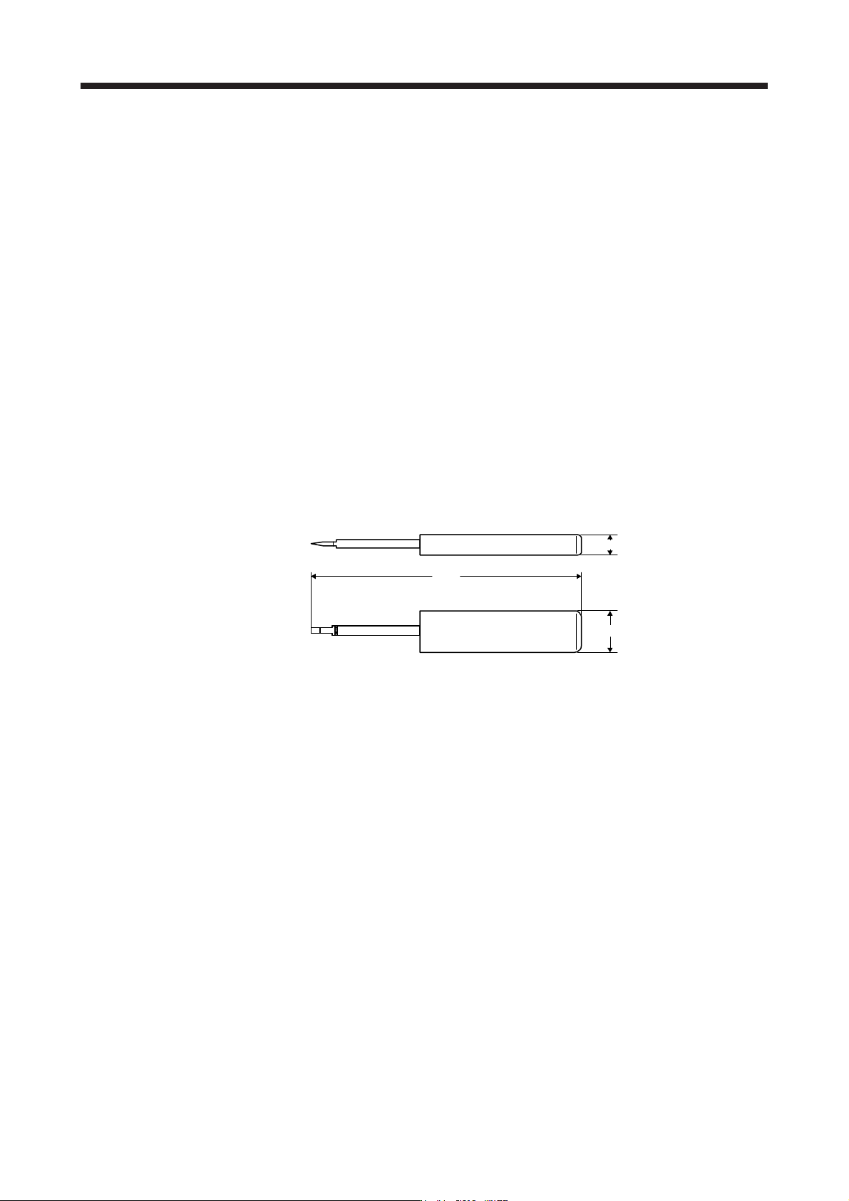
(a) Using extraction tool (1891348-1 or 2040798-1)
1) Dimensions and mass
[Unit: mm]
100
15
7
Mass: Approx. 20 g
APPENDIX
App. - 15
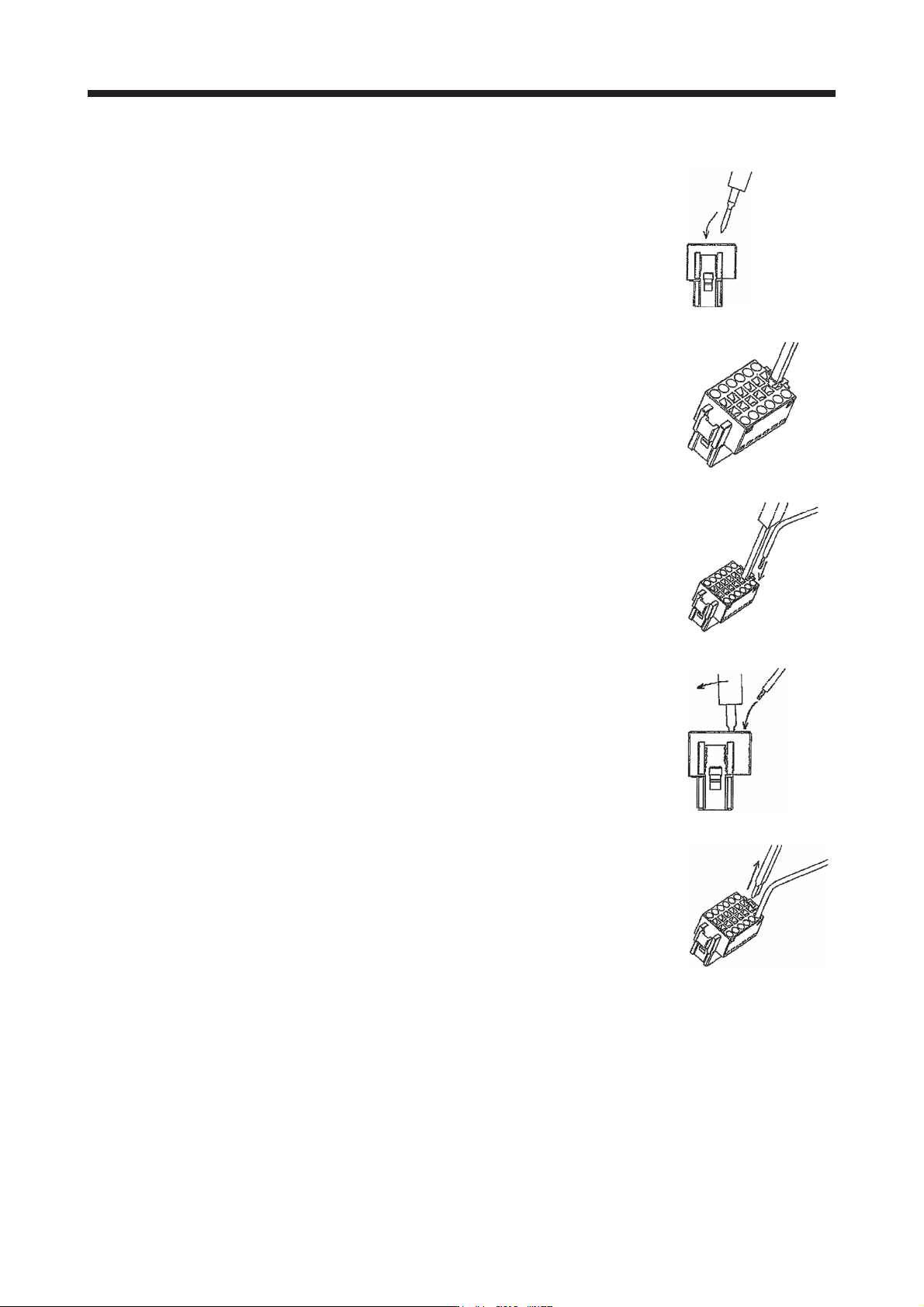
2) Connecting wires
a) Confirm the model number of the housing, contact and tool to be used.
b) Insert the tool diagonally into the receptacle assembly.
c) Insert the tool until it hits the surface of the receptacle assembly. At this
stage, the tool is vertical to the receptacle assembly.
d) Insert wires in the wiring hole till the end. The wires should be slightly
twisted in advance to prevent it from being loose.
It is easy to insert the wire if the wire is inserted diagonally while twisting
the tool.
e) Remove the tool.
APPENDIX
App. - 16
(b) Using a screwdriver
To avoid damaging housings and springs when wiring with screwdriver, do not put excessive force.
Be cautious when connecting.
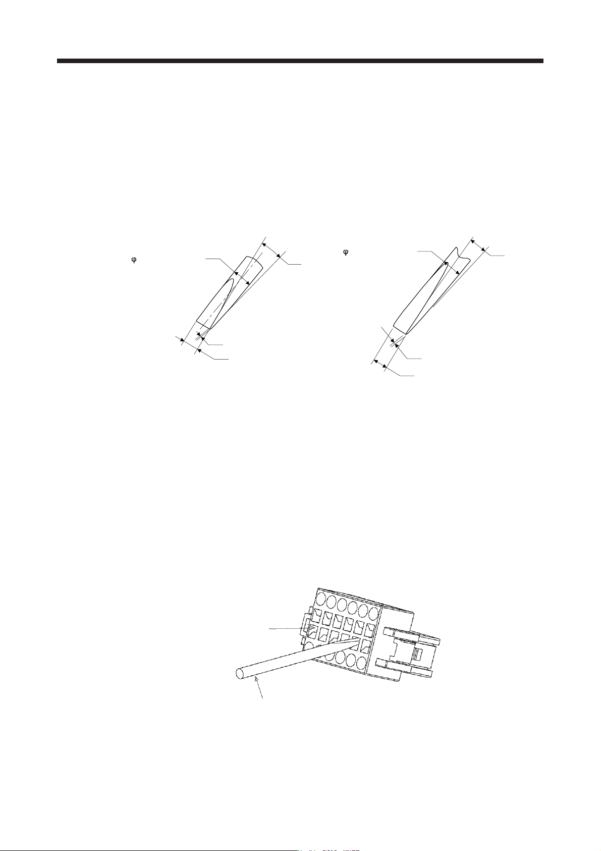
1) Adjusting screw driver
Diameter: 2.3 mm ± 0.05 mm
Length: 120 mm or less
Width: 2.3 mm
Thickness: 0.25 mm
Angle in tip of the blade: 18 ± 1 degrees
2.3 mm ± 0.05 mm
0.25 mm
2.3 mm
18° ± 1°
Diameter: 2.5 mm ± 0.05 mm
Length: 120 mm or less
Width: 2.5 mm
Thickness: 0.3 mm
Angle in tip of the blade: 12 ± 1 degrees
0.3 mm
2.5 mm
12° ± 1°
2.5 mm ± 0.05 mm
Screwdriver diameter: φ 2.3 mm Screwdriver diameter: φ 2.5 mm
2) Connecting wires
a) Insert a screwdriver in the front slot a little diagonally, and depress the spring. While
depressing the spring, insert the wires until they hit the end. Note that the housing and spring
may be damaged if the screwdriver is inserted strongly. Never insert the screwdriver in the
wire hole. Otherwise, the connector will be damaged.
b) Pull the screwdriver out while pressing the wires. Connecting wires is completed.
c) Pull the wire lightly to confirm that the wire is surely connected.
d) To remove the wires, depress the spring by the screwdriver in the same way as connecting
wires, and then pull the wires out.
Tool insertion slot
Screw driver