sh030106u.pdf - 第103页
3. SIG NALS A ND WIRI NG 3 - 26 3.5 Sig nal (dev ice) expla nations For the I/O in terfaces (s ymbols in I/O divis ion colu mn i n the t ab le), refer to s ection 3.8. 2. The pin num bers in the co nnector pin No. c olum…
3. SIGNALS AND WIRING
3 - 25
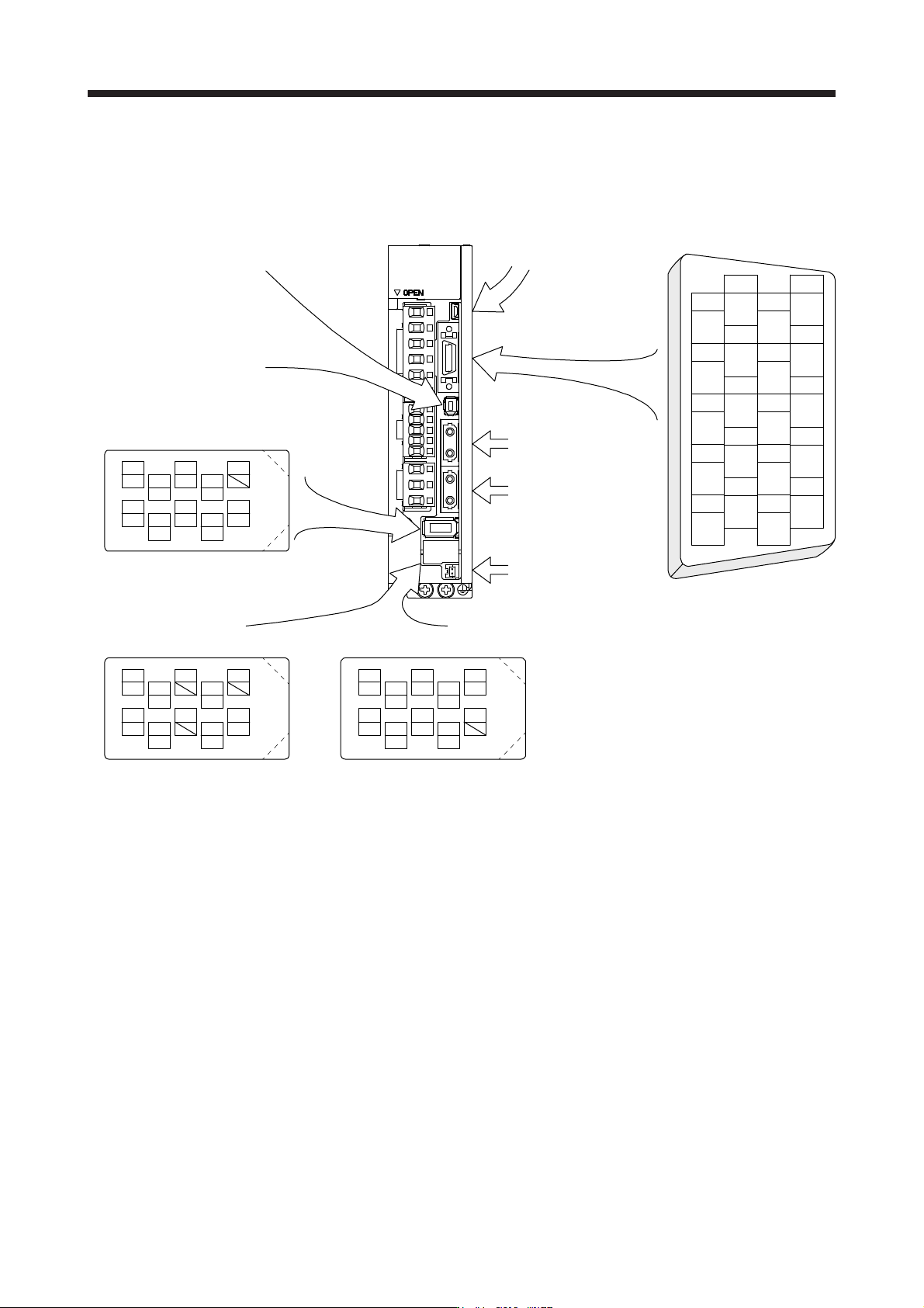
The servo amplifier front view shown is that of the MR-J4-20B or less. Refer to chapter 9 DIMENSIONS for
the appearances and connector layouts of the other servo amplifiers.
The frames of the CN2 and CN3 connectors are connected to the protective earth terminal in the servo
amplifier.
CN3
1
2
3
5
4
6
7
9
8
10
11
12
13
14
15
16
17
18
19
20
DI1
MO1
DICOM
LG
DOCOM
DICOM
LZ
DI2
MO2
EM2
LG
MBR
LBR
LA
LB
LZR
LAR
ALM
DI3INP
4
MRR
2
LG 8
6
1
P5
5
10
3
MR
7
9
BAT
MXR
MX
CN8
4
MRR2
2
LG 8
6
1
P5
5
10
3
MR2
7
9
MXR2
MX2
CN2L (Note 1, 2)
4
PAR
2
LG 8
6
1
P5
5
10
3
PA
7
9
PB
PZR
PZ
PBR PSEL
(for using serial encoder)
CN2L (Note 1, 2)
(for using A/B/Z-phase pulse encoder)
THM2
THM1
CN2 (Note 2)
CN5 (USB connector)
Refer to section 11.7
CN1A
Connector for SSCNET III
cable for previous servo
amplifier axis
CN1B
Connector for SSCNET III
cable for next servo
amplifier axis
CN4
(Battery connector)
Refer to section 11.8
For the STO I/O signal
connector, refer to section 13.2.
BAT
Note 1. The MR-J4-_B_ servo amplifiers have CN2L connectors. This CN2L is a connector of 3M.
When usin
g
an
y
other connector, refer to each servo motor instruction manual.
2. Refer to table 1.1 and "Linear Encoder Instruction Manual" for connections of external encoders.
3. SIGNALS AND WIRING
3 - 26
3.5 Signal (device) explanations
For the I/O interfaces (symbols in I/O division column in the table), refer to section 3.8.2.
The pin numbers in the connector pin No. column are those in the initial status.
3.5.1 Input device
Device Symbol
Connector
pin No.
Function and application
I/O
division
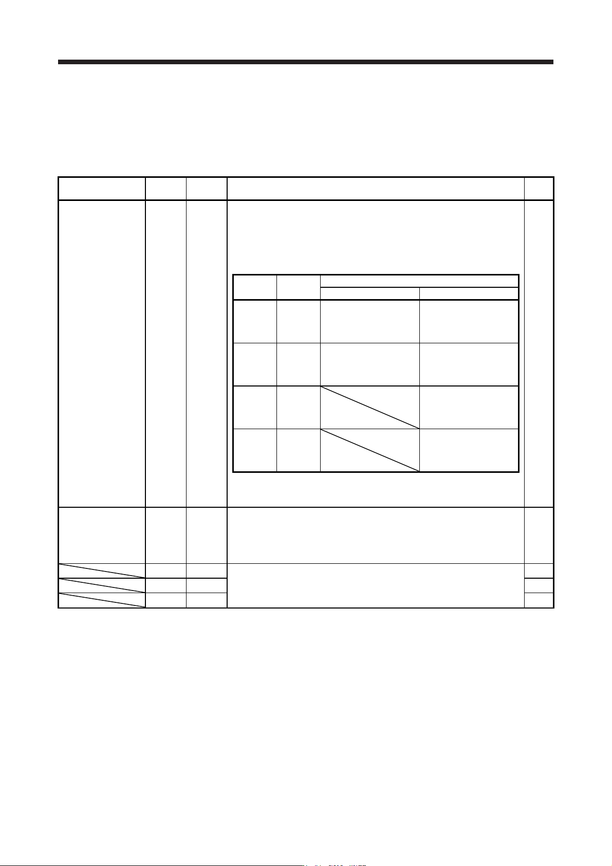
Forced stop 2 EM2 CN3-20
Turn off EM2 (open between commons) to decelerate the servo motor to a stop
with commands.
Turn EM2 on (short between commons) in the forced stop state to reset that
state.
Set [Pr. PA04] to "2 1 _ _" to disable EM2.
The following shows the setting of [Pr. PA04].
DI-1
[Pr. PA04]
setting
EM2/EM1
Deceleration method
EM2 or EM1 is off Alarm occurred
0 0 _ _ EM1
MBR (Electromagnetic
brake interlock) turns off
without the forced stop
deceleration.
MBR (Electromagnetic
brake interlock) turns off
without the forced stop
deceleration.
2 0 _ _ EM2
MBR (Electromagnetic
brake interlock) turns off
after the forced stop
deceleration.
MBR (Electromagnetic
brake interlock) turns off
after the forced stop
deceleration.
0 1 _ _
Not using
EM2 and
EM1
MBR (Electromagnetic
brake interlock) turns off
without the forced stop
deceleration.
2 1 _ _
Not using
EM2 and
EM1
MBR (Electromagnetic
brake interlock) turns off
after the forced stop
deceleration.
EM2 and EM1 are mutually exclusive.
EM2 has the same function as EM1 in the torque control mode.
Forced stop 1 EM1 (CN3-20) When using EM1, set [Pr. PA04] to "0 0 _ _" to enable EM1.
When EM1 is turned off (open between commons), the base circuit shuts off,
and the dynamic brake operates to decelerate the servo motor to a stop.
The forced stop will be reset when EM1 is turned on (short between commons).
Set [Pr. PA04] to "0 1 _ _" to disable EM1.
DI-1
DI1 CN3-2
Devices can be assigned for these signals with controller setting. For devices
that can be assigned, refer to the controller instruction manual. The following
devices can be assigned for MR-J4 compatible controller (R_MTCPU,
Q17_DSCPU, RD77MS_ and QD77MS_).
DI-1
DI2 CN3-12 DI-1
DI3 CN3-19 DI-1
3. SIGNALS AND WIRING
3 - 27
3.5.2 Output device
(1) Output device pin
The following shows the output device pins and parameters for assigning devices.
Connector pin No. Parameter Initial device I/O division
CN3-13 [Pr. PD07] MBR
CN3-9 [Pr. PD08] INP DO-1
CN3-15 [Pr. PD09] ALM
(2) Output device explanations
Device Symbol Function and application
Electromagnetic
brake interlock
MBR When using the device, set operation delay time of the electromagnetic brake in [Pr. PC02].
When a servo-off status or alarm occurs, MBR will turn off.
Malfunction ALM When the protective circuit is activated to shut off the base circuit, ALM will turn off.
When an alarm does not occur, ALM will turn on after 2.5 s to 3.5 s after power-on.
In-position INP
When the number of droop pulses is in the in-position range, INP will turn on. The in-position range
can be changed using [Pr. PA10]. When the in-position range is increased, INP may be on during
low-speed rotation.
The device cannot be used in the speed control mode, torque control mode, and for continuous
operation to torque control mode.
Dynamic brake
interlock
DB When using the signal, enable it by the setting of [Pr. PD07] to [Pr. PD09].
DB turns off when the dynamic brake needs to operate. When using the external dynamic brake on
the servo amplifier of 11 kW or more, this device is required. (Refer to section 11.17.)
For the servo amplifier of 7 kW or less, it is not necessary to use this device.
The external dynamic brake cannot be used with 11 kW or more servo amplifier for compliance
with SEMI-F47 standard. Do not assign DB (Dynamic brake interlock) in [Pr. PD07] to [Pr. PD09].
Failure to do so will cause the servo amplifier to become servo-off when an instantaneous power
failure occurs.
Ready RD Enabling servo-on to make the servo amplifier ready to operate will turn on RD.
Speed reached SA
SA will turn off during servo-off. When the servo motor speed reaches the following range, SA will
turn on. Set speed ± ((Set speed × 0.05) + 20) r/min
When the preset speed is 20 r/min or less, SA always turns on.
The device cannot be used in the position control mode and torque control mode.
Limiting speed VLC
When the speed reaches the speed limit value in the torque control mode, VLC will turn on. When
the servo is off, TLC will be turned off.
The device cannot be used in the position control mode and speed control mode.
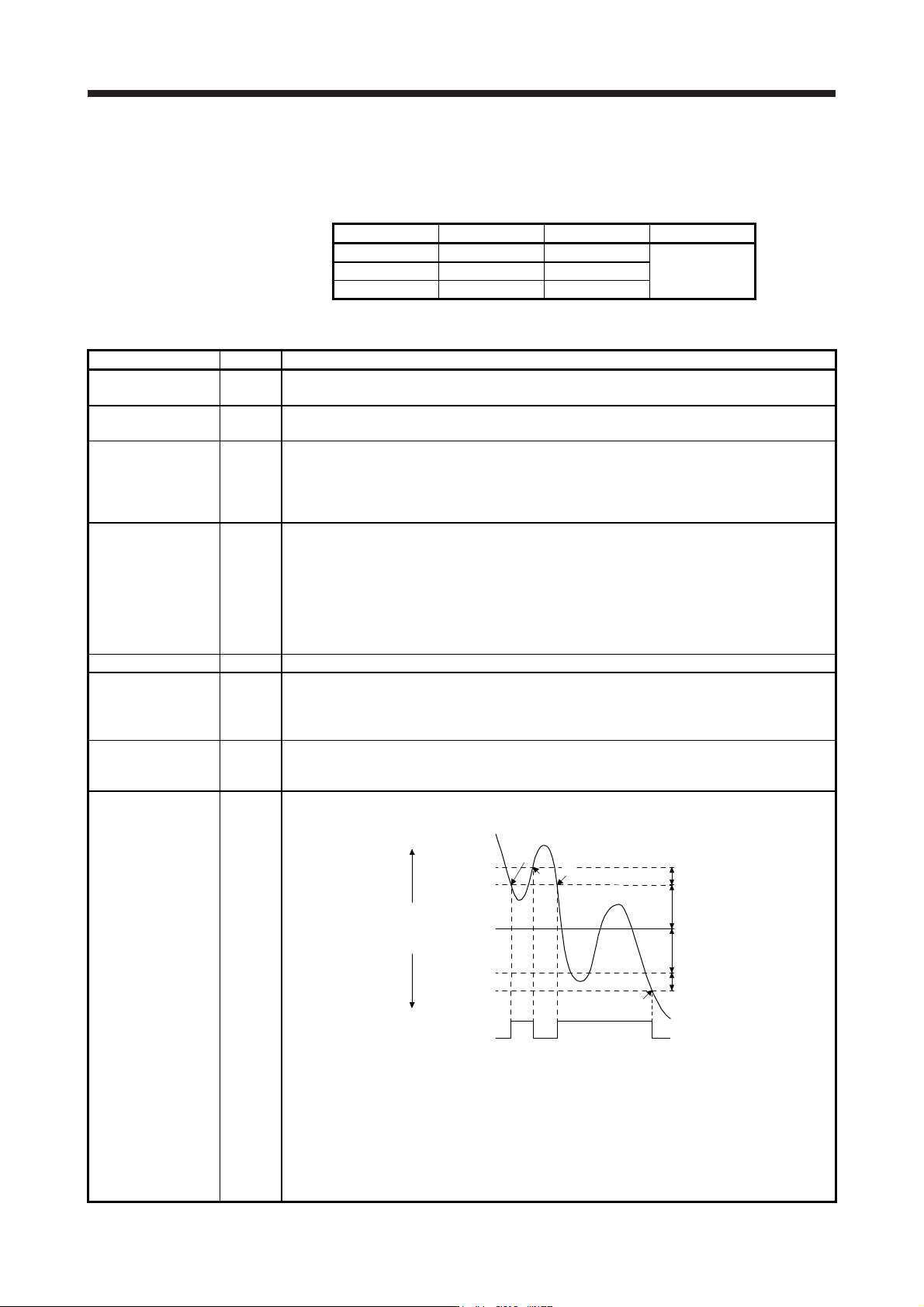
Zero speed detection ZSP
ZSP turns on when the servo motor speed is zero speed (50 r/min) or less. Zero speed can be
changed with [Pr. PC07].
OFF
ON
Servo motor
speed
20 r/min
(Hysteresis width)
[Pr. PC07]
20 r/min
(Hysteresis width)
OFF level
-70 r/min
ON level
-50 r/min
ON level
50 r/min
OFF level
70 r/min
0 r/min
[Pr. PC07]
ZSP
(Zero speed
detection)
1)
3)
2)
4)
Forward
rotation
direction
Reverse
rotation
direction
ZSP will turn on when the servo motor is decelerated to 50 r/min (at 1)), and will turn off when the
servo motor is accelerated to 70 r/min again (at 2)).
ZSP will turn on when the servo motor is decelerated again to 50 r/min (at 3)), and will turn off
when the servo motor speed has reached -70 r/min (at 4)).
The range from the point when the servo motor speed has reached on level, and ZSP turns on, to
the point when it is accelerated again and has reached off level is called hysteresis width.
Hysteresis width is 20 r/min for this servo amplifier.
When you use a linear servo motor, [r/min] explained above will be [mm/s].