sh030106u.pdf - 第134页
4. STA RTUP 4 - 9 (2) Disabling cont rol axis switch (SW2-2) Turning " ON (up) " the dis ab ling contr ol ax is switc h disa bles t h e cor respondi ng ser vo motor. The serv o motor wil l be dis abled-axis sta…
4. STARTUP
4 - 8
4.3 Switch setting and display of the servo amplifier
Switching to the test operation mode, deactivating control axes, and setting control axis No. are enabled with
switches on the servo amplifier.
On the servo amplifier display (three-digit, seven-segment LED), check the status of communication with the
servo system controller at power-on, and the axis number, and diagnose a malfunction at occurrence of an
alarm.
4.3.1 Switches
WARNING
When switching the axis selection rotary switch (SW1) and auxiliary axis number
setting switch (SW2), use insulated screw driver. Do not use a metal screw driver.
Touching patterns on electronic boards, lead of electronic parts, etc. may cause
an electric shock.
POINT
Turning "ON (up)" all the control axis setting switches (SW2) enables an
operation mode for manufacturer setting and displays "off". The mode is not
available. Set the control axis setting switches (SW2) correctly according to this
section.
Cycling the main circuit power supply and control circuit power supply enables
the setting of each switch.
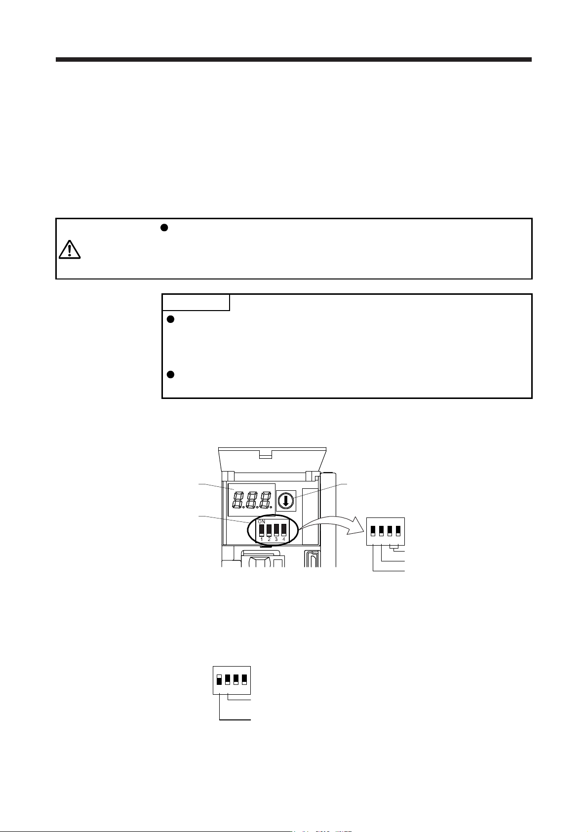
The following explains the test operation select switch, the disabling control axis switch, auxiliary axis
number setting switches, and the axis selection rotary switch.
3-digit, 7-segment LED
Control axis setting switch
(SW2)
Axis selection rotary switch
(SW1)
Auxiliary axis number setting switch
Disabling control axis switch
Test operation select switch
1
ON
2 3 4
(1) Test operation select switch (SW2-1)
To use the test operation mode, turn "ON (up)" the switch. Turning "ON (up)" the switch enables the test
operation mode. In the test operation mode, the functions such as JOG operation, positioning operation,
and machine analyzer are available with MR Configurator2. Before turning "ON (up)" the test operation
select switch, turn "OFF (down)" the disabling control axis switch.
Disabling control axis switch
Set to the "OFF (down)" position.
Test operation select switch
Set to the "ON (up)" position.
1
ON
2 3 4
4. STARTUP
4 - 9
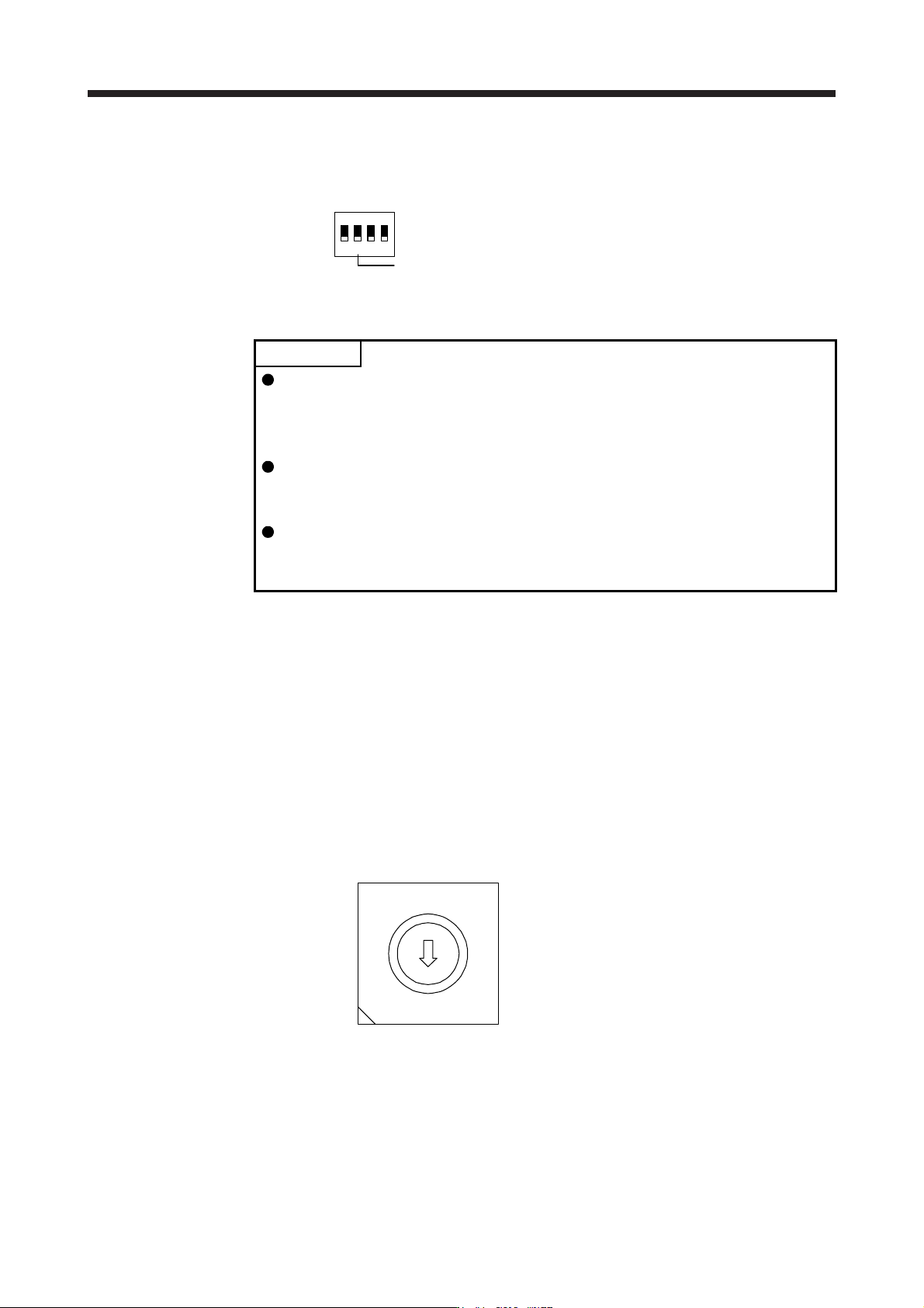
(2) Disabling control axis switch (SW2-2)
Turning "ON (up)" the disabling control axis switch disables the corresponding servo motor. The servo
motor will be disabled-axis status and will not be recognized by the controller.
Disabling control axis switch
1
ON
2 3 4
(3) Switches for setting control axis No.
POINT
The control axis No. set to the auxiliary axis number setting switches (SW2-3
and SW2-4) and the axis selection rotary switch (SW1) should be the same as
the one set to the servo system controller. The number of the axes you can set
depends on the servo system controller.
For setting the axis selection rotary switch, use a flat-blade screwdriver with the
blade edge width of 2.1 mm to 2.3 mm and the blade edge thickness of 0.6 mm
to 0.7 mm.
When the test operation mode is selected with the test operation select switch
(SW2-1), the SSCNET III/H communication for the servo amplifier in the test
operation mode and the following servo amplifiers is blocked.
You can set the control axis No. between 1 and 64 by using auxiliary axis number setting switches with
the axis selection rotary switch. (Refer to (3) (c) in this section.)
If the same numbers are set to different control axes in a single communication system, the system will
not operate properly. The control axes may be set independently of the SSCNET III cable connection
sequence. The following shows the description of each switch.
(a) Auxiliary axis number setting switches (SW2-3 and SW2-4)
Turning these switches "ON (up)" enables you to set the axis No. 17 or more.
(b) Axis selection rotary switch (SW1)
You can set the control axis No. between 1 and 64 by using auxiliary axis number setting switches
with the axis selection rotary switch. (Refer to (3) (c) in this section.)
8
7
6
5
4
3
2
1
0
F
E
D
C
B
A
9
A
xis selection rotary switch (SW1)
4. STARTUP
4 - 10
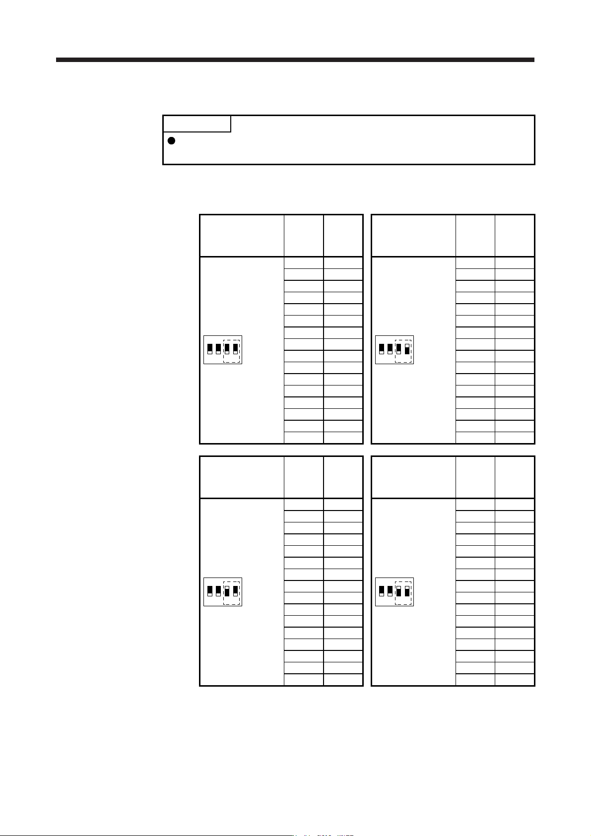
(c) Switch combination list for the control axis No. setting
POINT
Set control axis Nos. for one system. For details of the control axis No., refer to
the servo system controller user's manual.
The following lists show the setting combinations of the auxiliary axis number setting switches and
the axis selection rotary switch.
Auxiliary axis number
setting switch
Axis
selection
rotary
switch
Control
axis No.
Auxiliary axis number
setting switch
Axis
selection
rotary
switch
Control
axis No.
1
ON
2 3 4
0 1
1
ON
2 3 4
0 17
1 2 1 18
2 3 2 19
3 4 3 20
4 5 4 21
5 6 5 22
6 7 6 23
7 8 7 24
8 9 8 25
9 10 9 26
A 11 A 27
B 12 B 28
C 13 C 29
D 14 D 30
E 15 E 31
F 16 F 32
Auxiliary axis number
setting switch
Axis
selection
rotary
switch
Control
axis No.
Auxiliary axis number
setting switch
Axis
selection
rotary
switch
Control
axis No.
1
ON
2 3 4
0 33
1
ON
2 3 4
0 49
1 34 1 50
2 35 2 51
3 36 3 52
4 37 4 53
5 38 5 54
6 39 6 55
7 40 7 56
8 41 8 57
9 42 9 58
A 43 A 59
B 44 B 60
C 45 C 61
D 46 D 62
E 47 E 63
F 48 F 64