sh030106u.pdf - 第444页
11. OPT I ONS AND PER IPH ERA L EQU IPM ENT 11 - 12 3 11.19.6 Wiring and per iphe ral op tions (1) Wire size POINT Selectio n requir emen ts for t he wire s ize ar e as foll ows. Wire ty pe: 600 V Grad e he at-resis tant…
11. OPTIONS AND PERIPHERAL EQUIPMENT
11 - 122
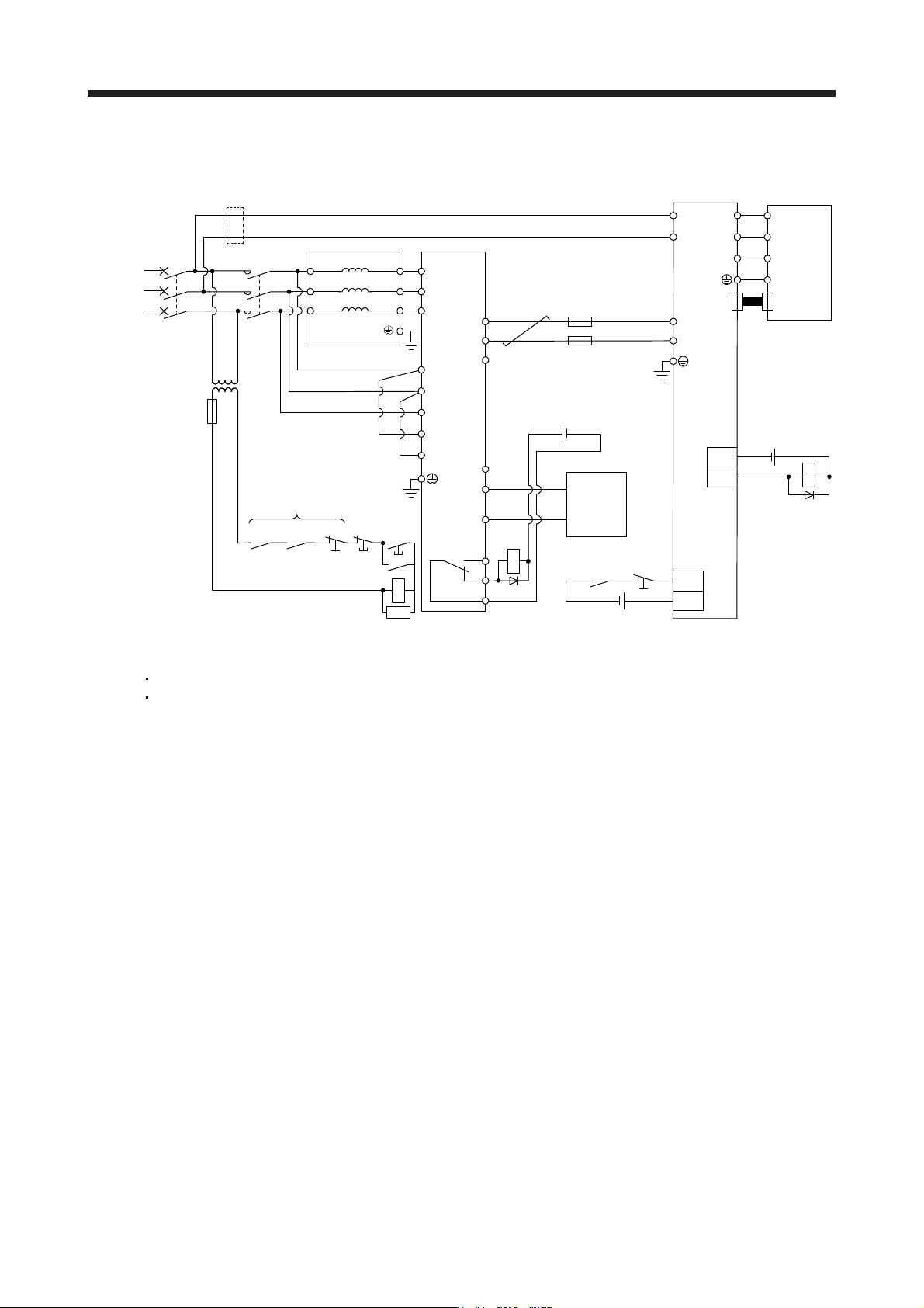
(2) 400
V class
T/L3
S/L2
R/L1
T2/L32
MCMCCB
S2/L22
R2/L12
FR-XCL-H
MC
RA2RA1
EM1
MC
SK
RA1
EM1
R2/L12
S2/L22
N/-
P4
RYB
RYA
SE
P/+
T2/L32
R/L1
S/L2
T/L3
L11
L21
P4
N-
U
V
W
EM1
R1/L11
S1/L21
U
V
W
E
CN2
FR-XC-H
DICOM
B
C
A
RA1
DOCOM
ALM
RA2
3-phase
380 V AC
to
480 V AC
Off
On
Servo motor
Servo amplifier
Controller
24 V DC
24 V DC
24 V DC
Step-down
transformer
(Note 6)
(Note 11)
(Note 10)
(Note 1)
(Note 8)
(Note 2)
(Note 9)
(Note 7)
(Note 7)
(Note 1)
(Note 3)
(Note 1, 5)
(Note 7)
(Note 4)
Note 1. Configure a sequence that shuts off the main circuit power supply in the following situations:
When an alarm occurs in the FR-XC-H or servo amplifier
When EM1
(
Forced stop 1
)
is enabled.
2. Confi
g
ure a sequence that shifts the status to servo-on once the F
R
-XC-H is read
y
.
3. Ensure that the servo motor stops with a forced stop input of the servo amplifier when an alarm occurs in the FR-XC-H. If t
he
controller does not have an emer
g
enc
y
stop input, use the forced stop input of the servo amplifier to stop the servo motor.
4. When usin
g
the FR-XC-H, remove the wire between P3 and P4.
5. To use EM1
(
Forced stop 1
)
, set [Pr. PA04] to "0 0 _ _".
6. If wires used for L11 and L21 are thinner than wires used for L1, L2, and L3, use a molded-case circuit breaker.
7.
A
lthough the diagram shows the input signal and the output signal each using a separate 24 V DC power supply for illustrative
purposes, the s
y
stem can be confi
g
ured to use a sin
g
le 24 V DC power suppl
y
.
8. Remove the R1/L11 and S1/L21
j
umpers when usin
g
a dedicated power suppl
y
for the control circuit.
9. Do not connect an
y
thin
g
to the P4 terminal of the FR-XC-H.
10. Install a fuse on each wire between the FR-XC-H and servo amplifier.
11. Make sure to wire the built-in regenerative resistor when using servo amplifiers with a capacity of 7 kW or less. (factory-wired)
(
3.5 kW or less: between P+ and D, 5 kW/7 kW: between P+ and C
)
11. OPTIONS AND PERIPHERAL EQUIPMENT
11 - 123
11.19.6
Wiring and peripheral options
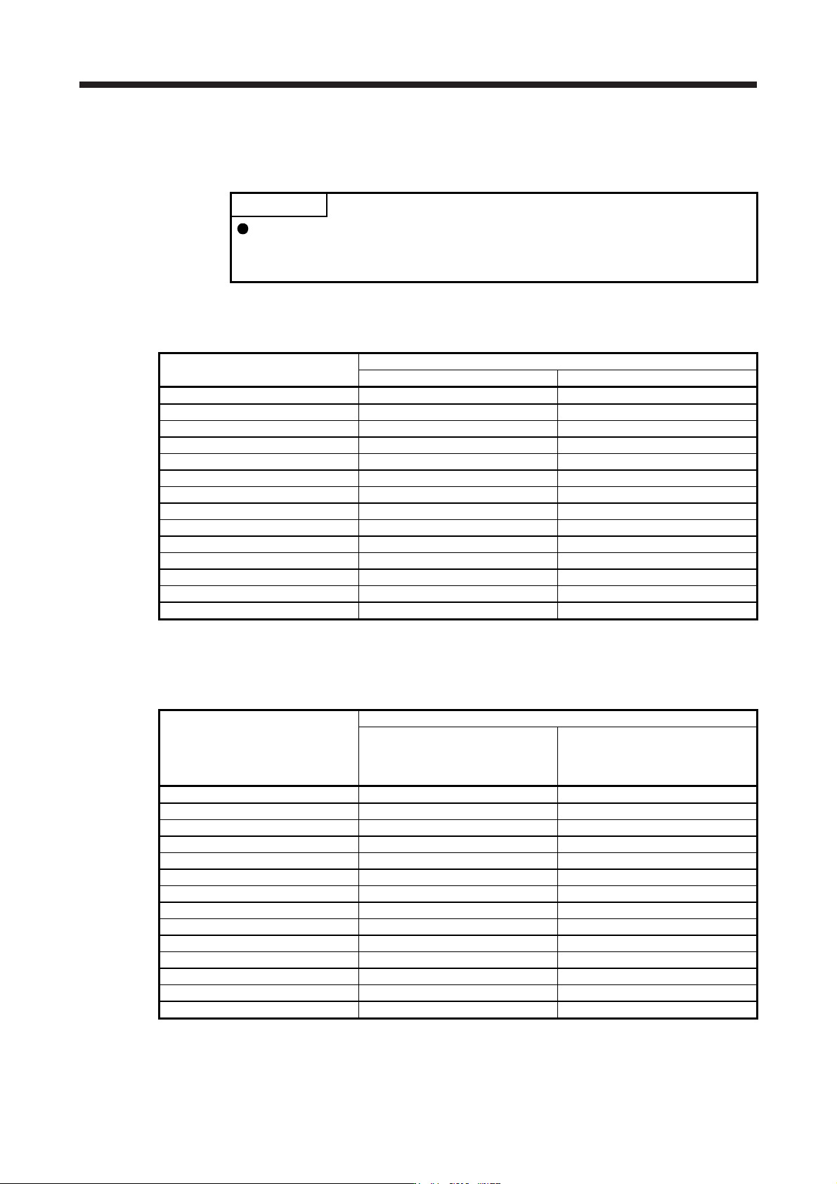
(1) Wire size
POINT
Selection requirements for the wire size are as follows.
Wire type: 600 V Grade heat-resistant polyvinyl chloride insulated wire (HIV wire)
Construction requirements: Single wire set in midair
(a)
Between P/+ and P4, and between N/- and N-
The following table shows the size of the wire between the FR-XC-(H) and servo amplifier.
Total capacity of servo amplifiers [kW]
Wire size [mm
2
]
200 V class 400 V class
1 or less 2 (AWG 14) 2 (AWG 14)
2 3.5 (AWG 12) 2 (AWG 14)
3.5 5.5 (AWG 10) 3.5 (AWG 12)
5 5.5 (AWG 10) 5.5 (AWG 10)
7 8 (AWG 8) 5.5 (AWG 10)
11 14 (AWG 6) 8 (AWG 8)
15 22 (AWG 4) 8 (AWG 8)
18.5 38 (AWG 2) 8 (AWG 8)
22 50 (AWG 1/0) 14 (AWG 6)
27.5 50 (AWG 1/0) 22 (AWG 4)
30 60 (AWG 2/0) 22 (AWG 4)
37 80 (AWG 3/0) 38 (AWG 2)
45 100 (AWG 4/0) 38 (AWG 2)
55 100 (AWG 4/0) 50 (AWG 1/0)
(b) G
rounding
The following table shows the size of the grounding wire for the FR-XC-(H). Use the shortest siz
e
wire possible.
Multifunction regeneration converter
Wire size [mm
2
]
Rated capacity of multifunction
regeneration converter ≥ Total
capacity of connected servo
amplifiers × 2
Rated capacity of multifunction
regeneration converter < Total
capacity of connected servo
amplifiers × 2
FR-XC-7.5K 8 (AWG 8) 8 (AWG 8)
FR-XC-11K 8 (AWG 8) 14(AWG 6)
FR-XC-15K 8 (AWG 8) 22 (AWG 4)
FR-XC-22K 22 (AWG 4) 38 (AWG 2)
FR-XC-30K 22 (AWG 4) 38 (AWG 2)
FR-XC-37K 38 (AWG 2) 60 (AWG 2/0)
FR-XC-55K 38 (AWG 2) 80 (AWG 3/0)
FR-XC-H7.5K 3.5 (AWG 12) 3.5 (AWG 12)
FR-XC-H11K 3.5 (AWG 12) 5.5 (AWG 10)
FR-XC-H15K 3.5 (AWG 12) 8 (AWG 8)
FR-XC-H22K 8 (AWG 8) 14 (AWG 6)
FR-XC-H30K 8 (AWG 8) 22 (AWG 4)
FR-XC-H37K 14 (AWG 6) 22 (AWG 4)
FR-XC-H55K 14 (AWG 6) 38 (AWG 2)
11. OPTIONS AND PERIPHERAL EQUIPMENT
11 - 124
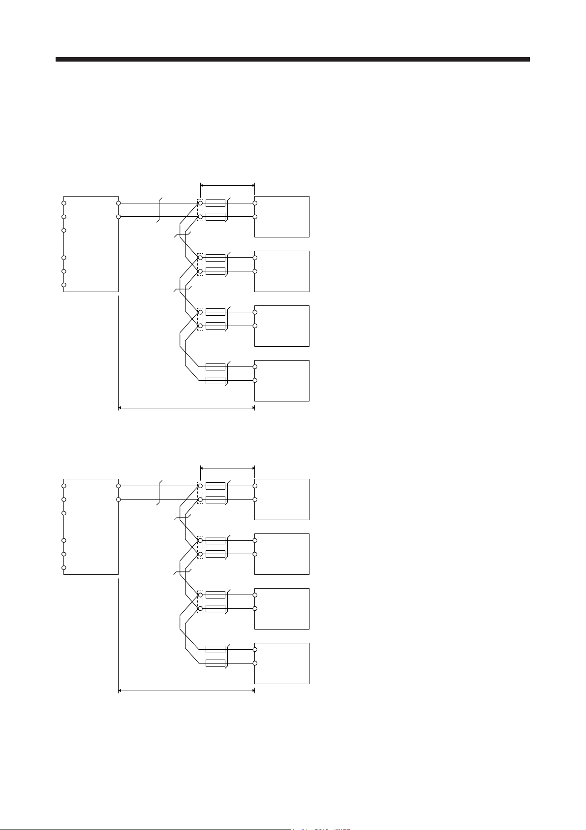
(2) Wir
e size selection example (between P/+ and P4, between N/- and N-)
When connecting multiple servo amplifiers to the FR-XC, junction terminal blocks must be used for the
wiring to terminals P4 and N- on the servo amplifiers. Connect the servo amplifiers in order with the
largest capacity first.
(a) 200 V class
R2/L12
S2/L22
T2/L32
R/L1
S/L2
T/L3
P/+
N/-
P4
N-
50 mm
2
P4
N-
P4
N-
P4
N-
22 mm
2
8 mm
2
22 mm
2
8 mm
2
5.5 mm
2
3.5 mm
2
FR-XC-55K Servo amplifier (15 kW)
First unit: Total of servo amplifier capacities
15 kW + 7 kW + 3.5 kW + 2.0 kW = 27.5 kW
50 mm
2
corresponding to 27.5 kW
Second unit: Total of servo amplifier capacities
7 kW + 3.5 kW + 2.0 kW = 12.5 kW
22 mm
2
corresponding to 15 kW
Third unit: Total of servo amplifier capacities
3.5 kW + 2.0 kW = 5.5 kW
8 mm
2
corresponding to 7 kW
Fourth unit: Total of servo amplifier capacities
2.0 kW = 2.0 kW
3.5 mm
2
corresponding to 2 kW
Servo amplifier (7 kW)
Servo amplifier (3.5 kW)
Servo amplifier (2 kW)
Total wiring length 5 m or shorter
Junction terminal
Wiring as short as possible
(b) 400
V class
R2/L12
S2/L22
T2/L32
R/L1
S/L2
T/L3
P/+
N/-
P4
N-
22 mm
2
P4
N-
P4
N-
P4
N-
8 mm
2
5.5 mm
2
8 mm
2
5.5 mm
2
3.5 mm
2
2 mm
2
FR-XC-H55K Servo amplifier (15 kW)
First unit: Total of servo amplifier capacities
15 kW + 7 kW + 3.5 kW + 2.0 kW = 27.5 kW
22 mm
2
corresponding to 27.5 kW
Second unit: Total of servo amplifier capacities
7 kW + 3.5 kW + 2.0 kW = 12.5 kW
8 mm
2
corresponding to 15 kW
Third unit: Total of servo amplifier capacities
3.5 kW + 2.0 kW = 5.5 kW
5.5 mm
2
corresponding to 7 kW
Fourth unit: Total of servo amplifier capacities
2.0 kW = 2.0 kW
2 mm
2
corresponding to 2 kW
Servo amplifier (7 kW)
Servo amplifier (3.5 kW)
Servo amplifier (2 kW)
Total wiring length 5 m or shorter
Junction terminal
Wiring as short as possible