sh030106u.pdf - 第514页
15. USIN G A DI REC T DRIV E MOTOR 15 - 11 2) Direct dr ive mot or move men t (whe n FLS and RL S are on) Magnetic pole detection completion position Servo-on position (Magnetic pole detection start position) Center of d…
15. USING A DIRECT DRIVE MOTOR
15 - 10
(3) Operation at the magnetic pole detection
WARNING
Note that the magnetic pole detection automatically starts simultaneously with the
turning-on of the servo-on command.
CAUTION
If the magnetic pole detection is not executed properly, the direct drive motor may
operate unexpectedly.
POINT
Establish the machine configuration using FLS (Upper stroke limit) and RLS
(Lower stroke limit). Otherwise, the machine may be damaged due to a collision.
At the magnetic pole detection, whether the motor rotates in the forward or
reverse direction is unpredictable.
Depending on the setting value of [Pr. PL09 Magnetic pole detection voltage
level], an overload, overcurrent, magnetic pole detection alarm, or others may
occur.
When performing the positioning operation from a controller, use the sequence
which confirms the normal completion of the magnetic pole detection and the
servo-on status, then outputs the positioning command. If the controller outputs
the positioning command before RD (Ready) turns on, the command may not be
accepted or a servo alarm may occur.
After the magnetic pole detection, check the positioning accuracy with the test
operation (positioning operation function) of MR Configurator2.
The accuracy of the magnetic pole detection improves with no load.
(a) Incremental system
POINT
For the incremental system, the magnetic pole detection is required every time
the power is turned on.
By turning on the servo-on command from the controller after the power-on, the magnetic pole
detection is automatically carried out. Therefore, there is no need to set the parameter (first digit of
[Pr. PL01]) for executing the magnetic pole detection.
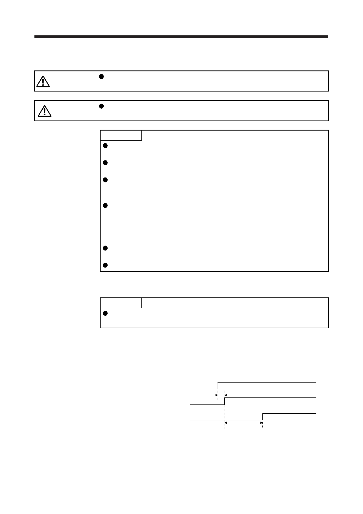
1) Timing chart
15 s or less
ON
OFF
ON
OFF
ON
OFF
95 ms
Servo-on command
Base circuit
RD (Ready)
Magnetic pole detection time (Note)
Note. The magnetic pole detection time indicates the operation time when FLS (Upper
stroke limit
)
and RLS
(
Lower stroke limit
)
are on.
15. USING A DIRECT DRIVE MOTOR
15 - 11
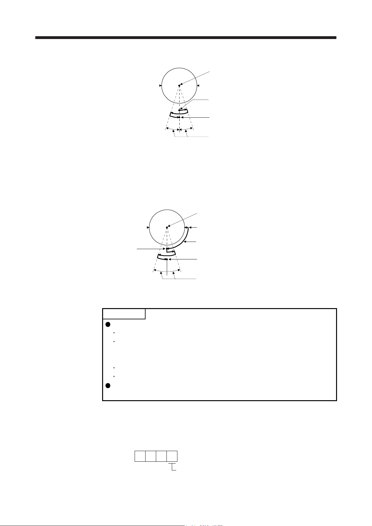
2) Direct drive motor movement (when FLS and RLS are on)
Magnetic pole detection completion position
Servo-on position (Magnetic pole detection start position)
Center of direct drive motor rotation part
FLS (Note)
(Note) RLS
10 degrees or less
Note. When you turn off FLS (Upper stroke limit) or RLS (Lower stroke limit) during the
magnetic pole detection, the magnetic pole detection is carried on to the opposite
direction. When FLS and RLS are off, [AL. 27 Initial magnetic pole detection error]
occurs.
3) Direct drive motor movement (when FLS or RLS is off)
When FLS or RLS is off at servo-on, the magnetic pole detection is carried out as follows.
Magnetic pole detection completion position
Magnetic pole detection
start position
After the machine moves to the position where the stroke limit
(FLS or RLS) is set, the magnetic pole detection starts.
Servo-on position
Center of direct drive motor rotation part
FLS
RLS
10 degrees or less
(b) Absolute position detection system
POINT
The magnetic pole detection is required in the following timings.
When the system is set up (at the first startup of equipment)
When the Z-phase pulse of the direct drive motor is not turned on at the
system setup (When the Z-phase pulse of the direct drive motor can be turned
on manually, the magnetic pole detection is not required.)
After a direct drive motor is replaced
When [AL. 25 Absolute position erased] has occurred
Turn on the Z-phase pulse of the direct drive motor in JOG operation from the
controller after the magnetic pole detection.
Perform the magnetic pole detection in the following procedure.
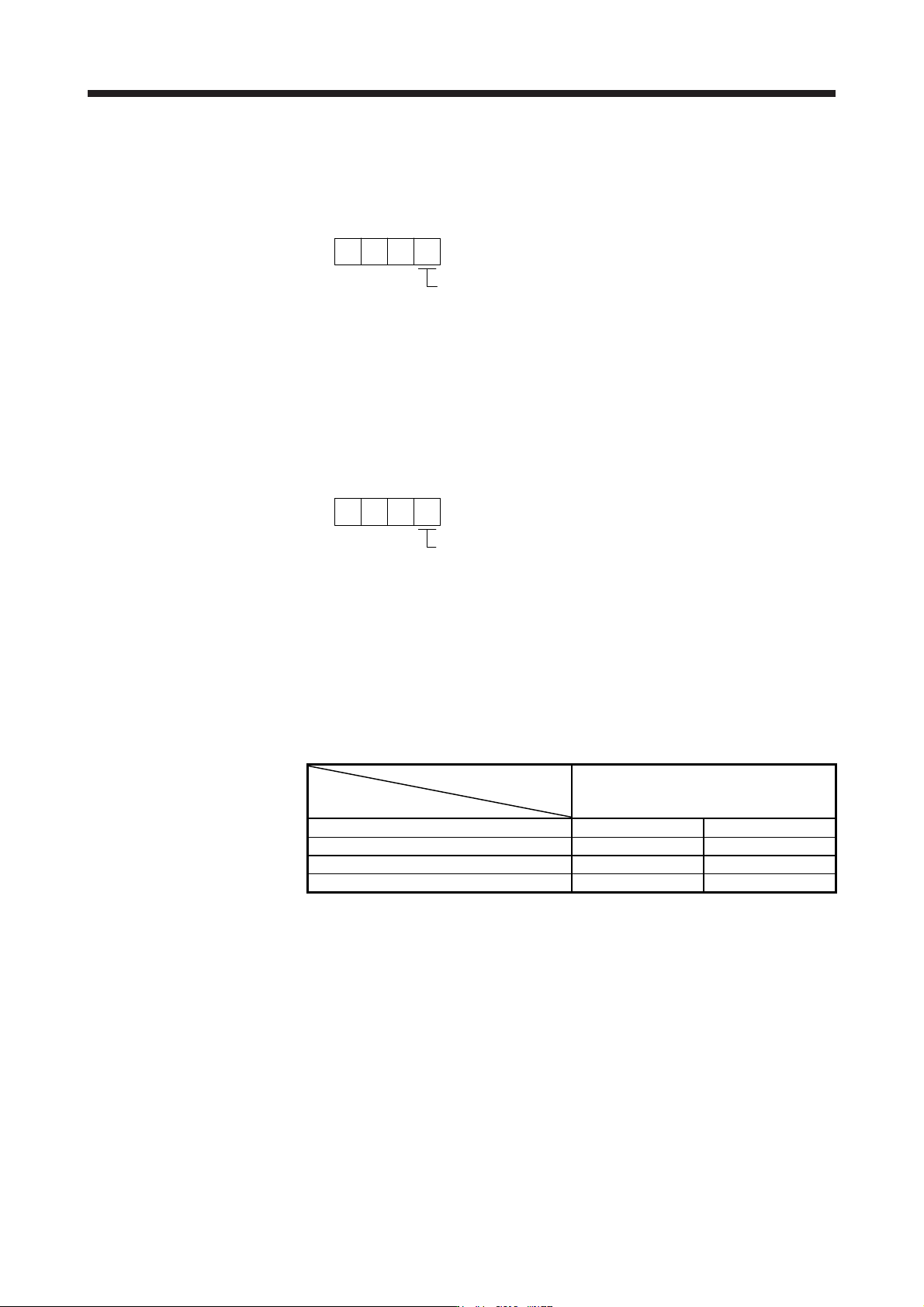
1) Set [Pr. PL01 Linear servo motor/DD motor function selection 1] to "_ _ _ 1" (Magnetic pole
detection at first servo-on).
[Pr. PL01]
Magnetic pole detection at first servo-on (initial value)
1
15. USING A DIRECT DRIVE MOTOR
15 - 12
2) Execute the magnetic pole detection. (Refer to (3) (a) in this section.)
3) After the completion of the magnetic pole detection, change [Pr. PL01] to "_ _ _ 0" (Magnetic pole
detection disabled).
[Pr. PL01]
Magnetic pole detection disabled
0
After the magnetic pole detection, by turning on the Z-phase pulse in JOG operation and by
disabling the magnetic pole detection function with [Pr. PL01], the magnetic pole detection after
each power-on is not required.
(4) Magnetic pole detection method setting
Set the magnetic pole detection method using the first digit of [Pr. PL08] (Magnetic pole detection
method selection).
[Pr. PL08]
Magnetic pole detection method selectio
n
0: Position detection method
4: Minute position detection method
(5) Setting of the magnetic pole detection voltage level by the position detection method
For the magnetic pole detection by the position detection method, set the voltage level with [Pr. PL09
Magnetic pole detection voltage level]. For the magnetic pole detection by the minute position detection
method, the voltage level setting is not required.
(a) Guideline of parameter settings
Set the parameters by referring to the following table.
[Pr. PL09] setting
(Guide value)
Servo status
Small ← Medium → Large
(10 or less (initial value) 50 or more)
Torques required for operation Small Large
Overload, overcurrent alarm Not frequently occurs Frequently occurs
Magnetic pole detection alarm Frequently occurs Not frequently occurs
Magnetic pole detection accuracy Low High
(b) Setting procedure
1) Perform the magnetic pole detection, and increase the setting value of [Pr. PL09 Magnetic pole
detection voltage level] until [AL. 50 Overload 1], [AL. 51 Overload 2], [AL. E1 Overload warning
1], and [AL. EC Overload warning 2] occur. Increase the setting value by five as a guide value.
When these alarms and warnings occur during the magnetic pole detection by using MR
Configurator2, the test operation of MR Configurator2 automatically completes and the servo-off
status is established.