sh030106u.pdf - 第387页
11. OPT ION S AND P ERI PHER AL EQU IPMENT 11 - 66 (4) Battery replace ment proc edure WARNING Before rep lacing a battery, turn off the main c ircuit pow er and wait for 15 minutes or longer u ntil the c harge l amp tur…
11. OPTIONS AND PERIPHERAL EQUIPMENT
11 - 65
(3) Battery mounting
POINT
One battery unit can be connected to up to 8-axis servo motors. However, when
using direct drive motors, the number of axes of the direct drive motors should
be up to 4 axes. Servo motors and direct drive motors in the incremental system
are included as the axis Nos. Linear servo motors are not counted as the axis
Nos.
The MR-J4W_-_B servo amplifiers can be combined with MR-J4-_B_(-RJ) servo
amplifiers. However, it cannot be used for MR-J4W2-0303B6.
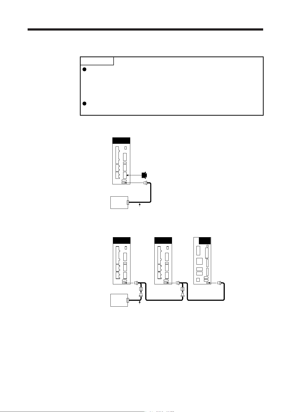
(a) When using 1-axis servo amplifier
CN1A
CN1B
Cap
CN4
CN10
MR-BT6VCASE
MR-BT6V1CBL_M
Servo amplifier
(b) When using up to 8-axis servo amplifiers
CN4
CN10
MR-BT6VCASE
MR-BT6V1CBL_M
MR-BT6V2CBL_M
Servo amplifier
(Last)
MR-BT6V2CBL_M
Servo amplifier
(First)
CN4 CN4
Servo amplifier
(Second)
11. OPTIONS AND PERIPHERAL EQUIPMENT
11 - 66
(4) Battery replacement procedure
WARNING
Before replacing a battery, turn off the main circuit power and wait for 15 minutes
or longer until the charge lamp turns off. Then, check the voltage between P+ and
N- with a voltage tester or others. Otherwise, an electric shock may occur. In
addition, when confirming whether the charge lamp is off or not, always confirm it
from the front of the servo amplifier.
CAUTION
The internal circuits of the servo amplifier may be damaged by static electricity.
Always take the following precautions.
Ground human body and work bench.
Do not touch the conductive areas, such as connector pins and electrical parts,
directly by hand.
POINT
Replacing battery with the control circuit power off will erase the absolute
position data.
Before replacing batteries, check that the new battery is within battery life.
Replace the battery while only control circuit power is on. Replacing battery with the control circuit power
on triggers [AL. 9F.1 Low battery]. However, the absolute position data will not be erased.
11. OPTIONS AND PERIPHERAL EQUIPMENT
11 - 67
(a) Assembling a battery unit
CAUTION
Do not mount new and old batteries together.
When you replace a battery, replace all batteries at the same time.
POINT
Always install five MR-BAT6V1 batteries to an MR-BT6VCASE battery case.
1) Required items
Product name Model
Quantity
Remark
Battery case MR-BT6VCASE 1
MR-BT6VCASE is a case used for connecting and
mounting five MR-BAT6V1 batteries.
Battery MR-BAT6V1 5 Lithium battery (primary battery, nominal + 6 V)
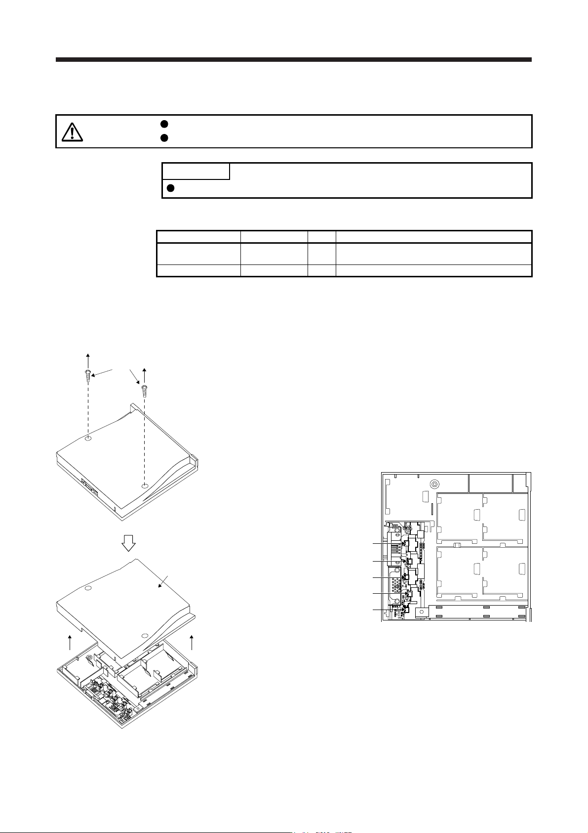
2) Disassembly and assembly of the battery case MR-BT6VCASE
a) Disassembly of the case
MR-BT6VCASE is shipped assembled. To mount MR-BAT6V1 batteries, the case needs to be
disassembled.
Threads
Remove the two screws using a
Phillips screwdriver.
CON2
CON3
CON1
CON4
CON5
Parts identification
BAT1
BAT2 BAT3
BAT4 BAT5
Cover
Remove the cover.