sh030106u.pdf - 第56页
1. FUNCTI ONS AND CONF IGURATION 1 - 39 1.8 Conf iguratio n inc luding perip heral eq uipment CAUTION Connectin g a servo motor of the wron g axis t o U, V, W, or CN2 o f the serv o amplif ier may caus e a ma lfunctio n.…
1. FUNCTIONS AND CONFIGURATION
1 - 38
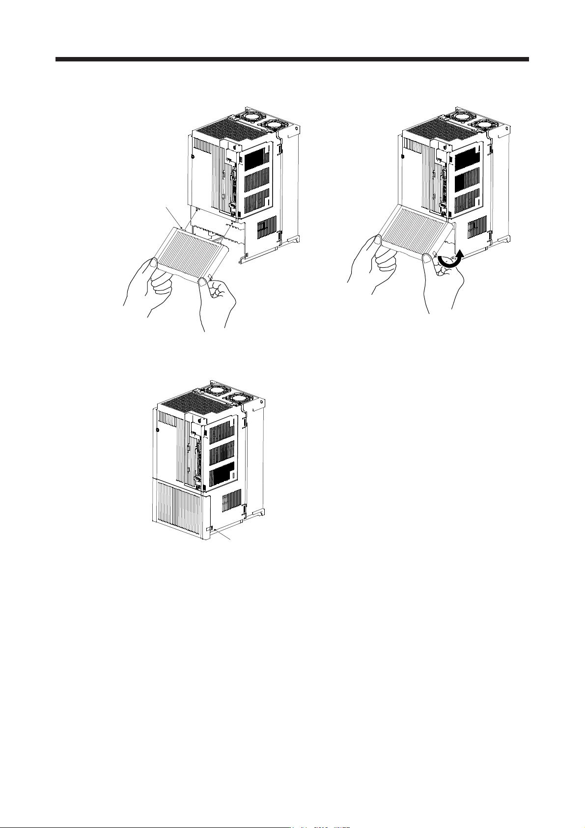
(2) Reinstallation of the front cover
Front cover
setting tab
A)
A)
1) Insert the front cover setting tabs into the sockets of
servo amplifier (2 places).
2) Push down the cover, supporting at point A).
Setting tab
3) Press the cover against the terminal box until the
installing knobs click.

1. FUNCTIONS AND CONFIGURATION
1 - 39
1.8 Configuration including peripheral equipment
CAUTION
Connecting a servo motor of the wrong axis to U, V, W, or CN2 of the servo
amplifier may cause a malfunction.
POINT
Equipment other than the servo amplifier and servo motor are optional or
recommended products.
When using the MR-J4-_B-RJ servo amplifier with the DC power supply input,
refer to app. 15.
1. FUNCTIONS AND CONFIGURATION
1 - 40
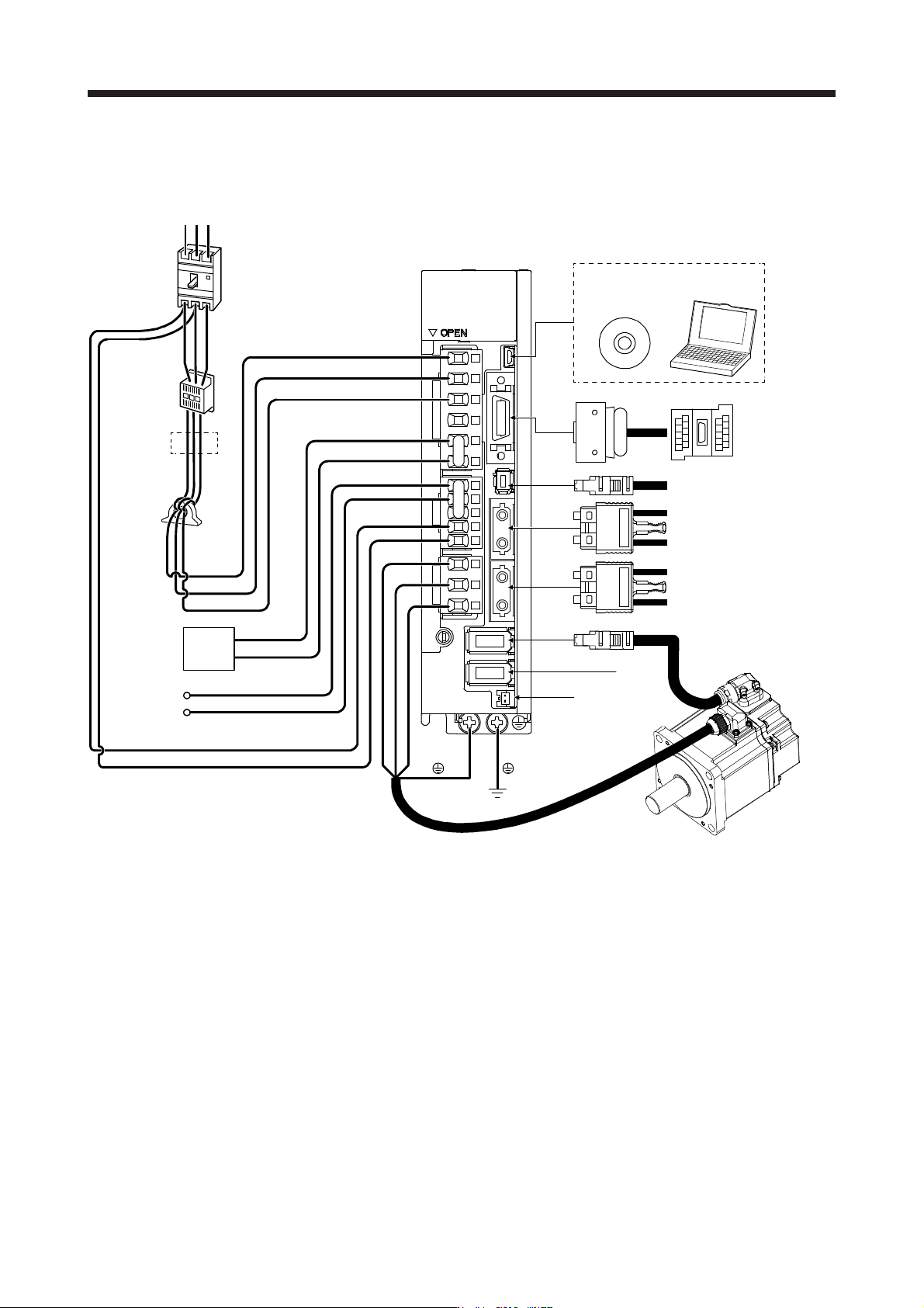
(1) 200 V class
(a) MR-J4-200B(-RJ) or less
The diagram is for MR-J4-20B-RJ.
CN4
CN5
P+
C
L11
L21
P3
P4
MR Configurator2
CN3
CN8
CN1A
CN1B
CN2
CN2L (Note 4)
W
V
U
L1
L2
L3
RS T
Line noise
filter
(FR-BSF01)
Regenerative
option
Servo motor
Personal
computer
Magnetic
contactor
(MC)
(Note 3)
(Note 1)
Power factor
improving DC
reactor
(FR-HEL)
Junction terminal
block
To safety relay or MR-J3-D05
safety logic unit
Servo system controller or
previous servo amplifier
CN1B
Next servo amplifier CN1A or
cap
Battery
Molded-case
circuit breaker
(MCCB)
Power supply
(Note 2)
D (Note 5)
Note 1. The power factor improving AC reactor can also be used. In this case, the power factor improving DC reactor cannot be used.
When not usin
g
the power factor improvin
g
DC reactor, short P3 and P4.
2. For 1-phase 200 V AC to 240 V AC, connect the power supply to L1 and L3. Leave L2 open. Refer to section 1.3 for the power
suppl
y
specifications.
3. Depending on the main circuit voltage and operation pattern, bus voltage decreases, and that may cause the forced stop
deceleration to shift to the dynamic brake deceleration. When dynamic brake deceleration is not required, slow the time to turn
off the ma
g
netic contactor.
4. This is for MR-J4-_B-RJ servo amplifier. MR-J4-_B servo amplifier does not have CN2L connector. When using MR-J4-_B-RJ
servo amplifier in the linear servo system or in the fully closed loop system, connect an external encoder to this connector.
Refer to table 1.1 and "Linear Encoder Instruction Manual" for the compatible external encoders.
5.
A
lwa
y
s connect between P+ and D terminals. When usin
g
the re
g
enerative option, refer to section 11.2.