sh030106u.pdf - 第244页
7. SPEC IAL ADJUSTMEN T FUNCT IONS 7 - 15 7.2 Gain s witchi ng functi on You can s witch ga ins w ith the func tion. You can s witch gains duri ng rotat ion and during s top, and c an use a control co mmand fr om a c ont…
7. SPECIAL ADJUSTMENT FUNCTIONS
7 - 14
(2) Parameter
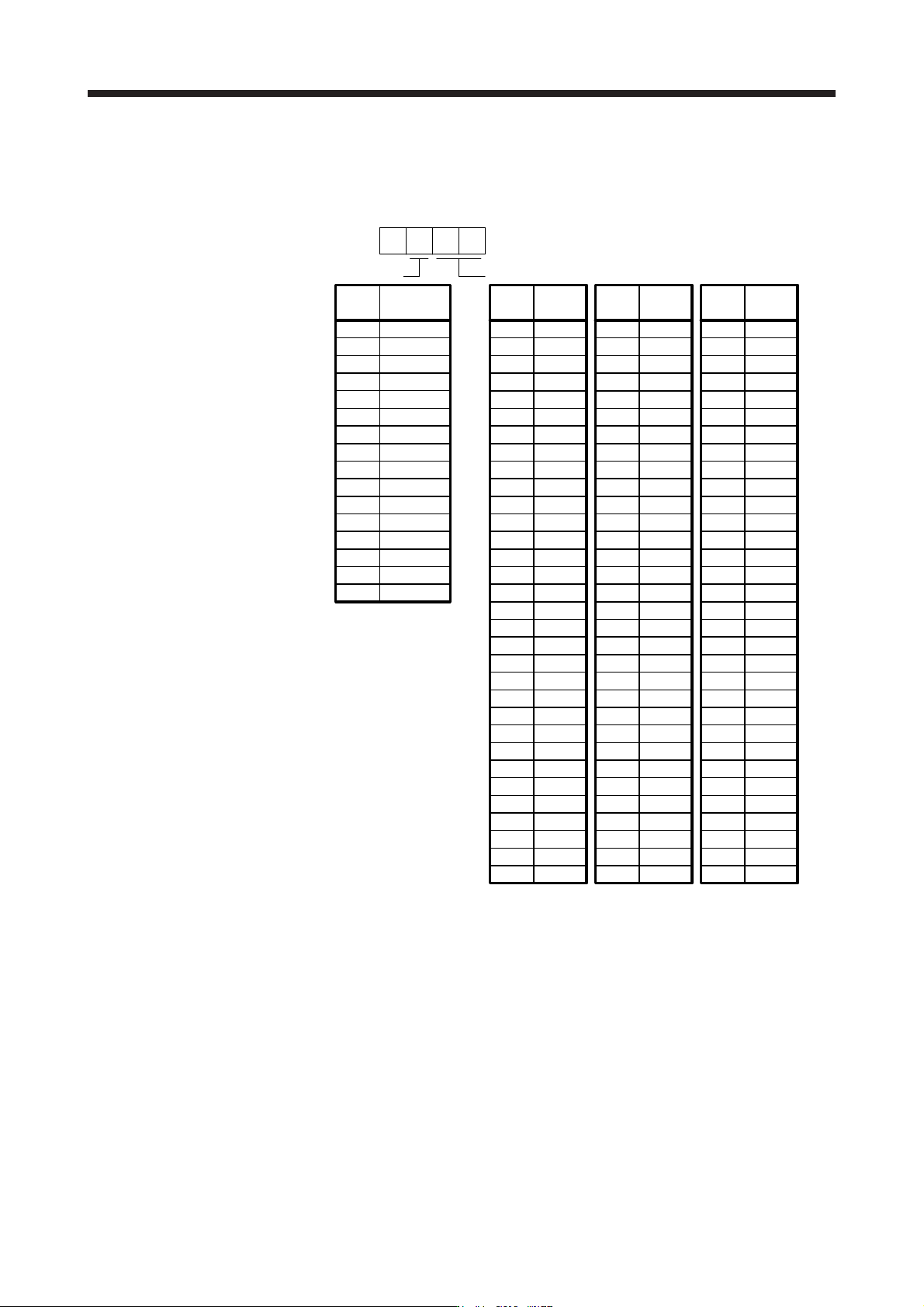
Set [Pr. PB45 Command notch filter] as shown below. For the command notch filter setting frequency,
set the closest value to the vibration frequency [Hz] at the load side.
Setting
value
Command notch filter setting frequency
Setting
value
Frequency
[Hz]
00
01
02
03
0
Frequency
[Hz]
Setting
value
Frequency
[Hz]
04
05
06
07
08
09
0A
0B
0C
0D
0E
0F
10
11
12
13
14
15
16
17
18
19
1A
1B
1C
1D
1E
1F
20
21
22
23
24
25
26
27
28
29
2A
2B
2C
2D
2E
2F
30
31
32
33
34
35
36
37
38
39
3A
3B
3C
3D
3E
3F
40
41
42
43
44
45
46
47
48
49
4A
4B
4C
4D
4E
4F
50
51
52
53
54
55
56
57
58
59
5A
5B
5C
5D
5E
5F
Disabled
2250
1125
750
562
450
375
321
281
250
225
204
187
173
160
150
140
132
125
118
112
107
102
97
93
90
86
83
80
77
75
72
70
66
62
59
56
53
51
48
46
45
43
41
40
38
37
36
35.2
33.1
31.3
29.6
28.1
26.8
25.6
24.5
23.4
22.5
21.6
20.8
20.1
19.4
18.8
18.2
17.6
16.5
15.6
14.8
14.1
13.4
12.8
12.2
11.7
11.3
10.8
10.4
10.0
9.7
9.4
9.1
8.8
8.3
7.8
7.4
7.0
6.7
6.4
6.1
5.9
5.6
5.4
5.2
5.0
4.9
4.7
4.5
Notch depth
0
1
2
3
4
5
6
7
8
9
A
B
C
D
E
F
Setting
value
Depth
[dB]
[Pr. PB45]
-40.0
-24.1
-18.1
-14.5
-12.0
-10.1
-8.5
-7.2
-6.0
-5.0
-4.1
-3.3
-2.5
-1.8
-1.2
-0.6

7. SPECIAL ADJUSTMENT FUNCTIONS
7 - 15
7.2 Gain switching function
You can switch gains with the function. You can switch gains during rotation and during stop, and can use a
control command from a controller to switch gains during operation.
7.2.1 Applications
The following shows when you use the function.
(1) You want to increase the gains during servo-lock but decrease the gains to reduce noise during rotation.
(2) You want to increase the gains during settling to shorten the stop settling time.
(3) You want to change the gains using a control command from a controller to ensure stability of the servo
system since the load to motor inertia ratio varies greatly during a stop (e.g. a large load is mounted on a
carrier).
7. SPECIAL ADJUSTMENT FUNCTIONS
7 - 16
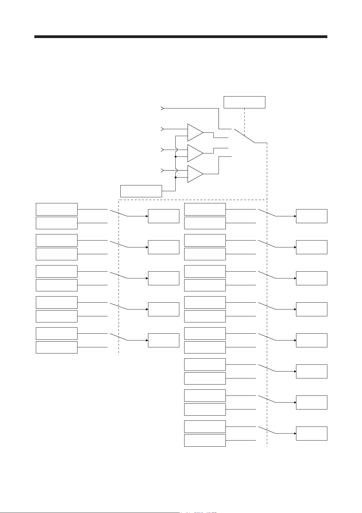
7.2.2 Function block diagram
The control gains, load to motor inertia ratio, and vibration suppression control settings are changed
according to the conditions selected by [Pr. PB26 Gain switching function] and [Pr. PB27 Gain switching
condition].
Command pulse
frequency
+
-
Droop pulses
Model speed
Control command
from controller
Comparator
Changing
CDP
[Pr. PB26]
+
-
+
-
GD2
[Pr. PB06]
GD2B
[Pr. PB29]
Enabled
GD2 value
PG1
[Pr. PB07]
PG1B
[Pr. PB60]
Enabled
PG1 value
PG2
[Pr. PB08]
PG2B
[Pr. PB30]
Enabled
PG2 value
VG2
[Pr. PB09]
VG2B
[Pr. PB31]
Enabled
VG2 value
VIC
[Pr. PB10]
VICB
[Pr. PB32]
Enabled
VIC value
VRF11
[Pr. PB19]
VRF11B
[Pr. PB33]
Enabled
VRF11 value
VRF12
[Pr. PB20]
VRF12B
[Pr. PB34]
Enabled
VRF12 value
CDL
[Pr. PB27]
VRF13
[Pr. PB21]
VRF13B
[Pr. PB35]
Enabled
VRF13 value
VRF14
[Pr. PB22]
VRF14B
[Pr. PB36]
Enabled
VRF14 value
VRF21
[Pr. PB52]
VRF21B
[Pr. PB56]
Enabled
VRF21 value
VRF22
[Pr. PB53]
VRF22B
[Pr. PB57]
Enabled
VRF22 value
VRF23
[Pr. PB54]
VRF23B
[Pr. PB58]
Enabled
VRF23 value
VRF24
[Pr. PB55]
VRF24B
[Pr. PB59]
Enabled
VRF24 value