sh030106u.pdf - 第681页
APPENDIX App. - 50 App. 14. 6 How to ch eck the country of orig in, and the year and month of man ufact ure The countr y of origi n, and t he year a nd mont h of manu facture ar e indic ated on the packagi ng box ( Fig. …
APPENDIX
App. - 49
App. 14 STO function with SIL 3 certification
The MR-J4 series general-purpose AC servo amplifiers now comply with safety integrity level 3 (SIL 3) of the
IEC 61508:2010 functional safety standard.
App. 14.1 Target models
MR-J4 series AC servo amplifiers (excluding MR-J4-03A6(-RJ) and MR-J4W2-0303B6)
App. 14.2 Change of the compliance
The target MR-J4 servo amplifiers now comply with SIL 3 (Table app. 3).
Table app. 3 Compliance with SIL 3
Before change After change
Safety performance
(Standards certified by CB)
EN ISO 13849-1:2015 Category 3 PL d,
IEC 61508 SIL 2,
EN 62061 SIL CL 2,
EN 61800-5-2 STO function
EN ISO 13849-1:2015 Category 3 PL e,
IEC 61508 SIL 3,
EN 62061 SIL CL 3,
EN 61800-5-2 STO function
App. 14.3 Schedule
For the products manufactured in Japan, this change has been made sequentially from the June 2015
production.
For the products manufactured and sold in China, this change has been made sequentially from the
December 2015 production.
There may be cases where both the former and new products exist in the distribution stage.
App. 14.4 Use with SIL 3
Set the safety level with [Pr. PF18 STO diagnosis error detection time].
To use the servo amplifier with SIL 3, set [Pr. PF18 STO diagnosis error detection time] within the range of 1
to 60, connect the TOFB output (CN8) of the servo amplifier to the input of a SIL 3-certified controller and
execute the diagnosis. SIL 3 functional safety of the servo amplifiers is certified by TÜV SÜD.
App. 14.5 Use with SIL 2 (as conventional)
The servo amplifiers are still capable of SIL 2 as before regardless of whether the STO diagnosis function is
enabled or not.
Either of the conventionally-used TÜV Rheinland certification or the new TÜV SÜD certification may be used.
APPENDIX
App. - 50
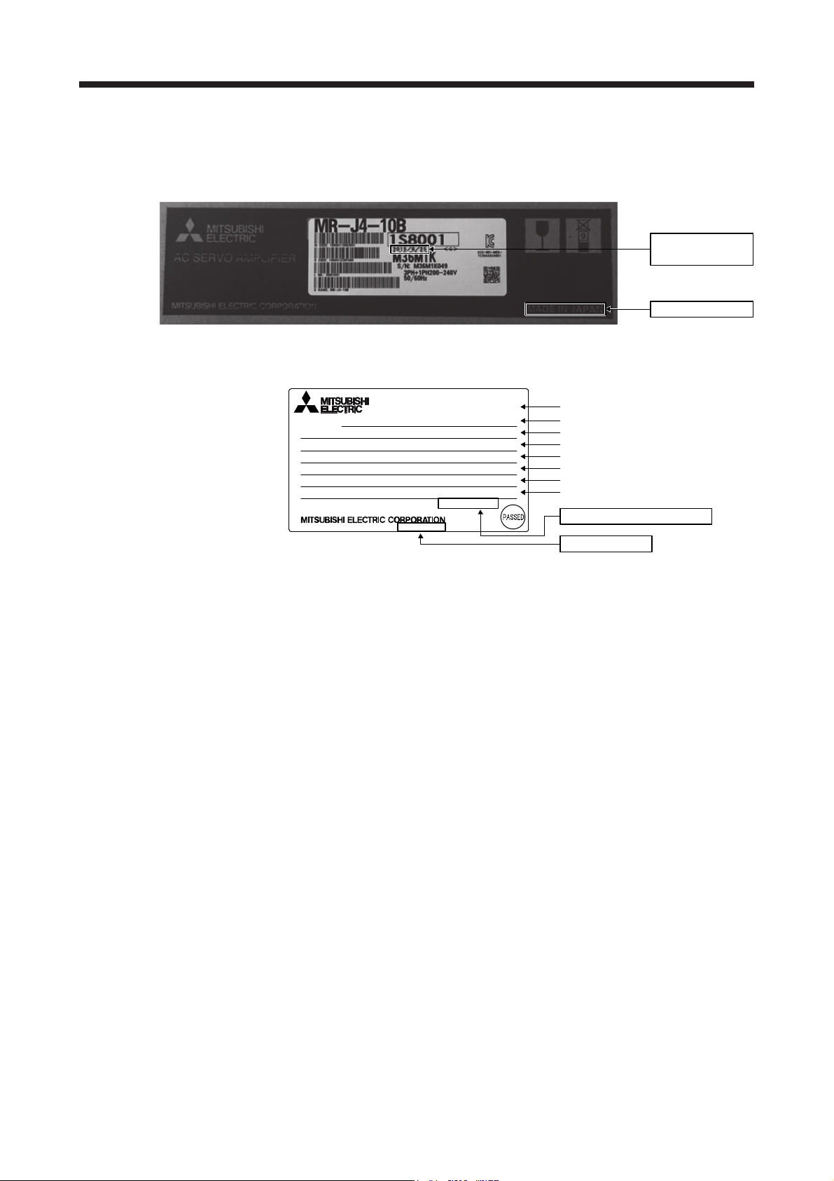
App. 14.6 How to check the country of origin, and the year and month of manufacture
The country of origin, and the year and month of manufacture are indicated on the packaging box (Fig. app.
3) and the rating plate (Fig. app. 4).
Manufacture month
and year
Country of origin
Fig. app. 3 Indication example on the packaging box
TOKYO 100-8310, JAPAN MADE IN JAPAN
Model
Capacity
Applicable power supply
Rated output current
Conforming standard, manual numbe
r
Ambient temperature
IP rating
Serial number
IP20
KCC-REI-MEK-TC300A624G51
Max. Surrounding Air Temp.: 55°C
POWER :100W
MR-J4-10B
AC SERVO
SER.A45001001
OUTPUT: 3PH170V 0-360Hz 1.1A
MAN.: IB(NA)0300175
INPUT : 3AC/AC200-240V 0.9A/1.5A 50/60Hz
STD.: IEC/EN 61800-5-1
DATE:2014-05
MODEL
Manufacture month and year
Country of origin
Fig. app. 4 Indication example on the rating plate
APPENDIX
App. - 51
App. 15 When using the servo amplifier with the DC power supply input
POINT
The DC power supply input is available with MR-J4-_B-RJ servo amplifiers with
software version C2 or later.
When using the MR-J4-_B-RJ servo amplifier with the DC power supply input,
set [Pr. PC20] to "_ _ _ 1".
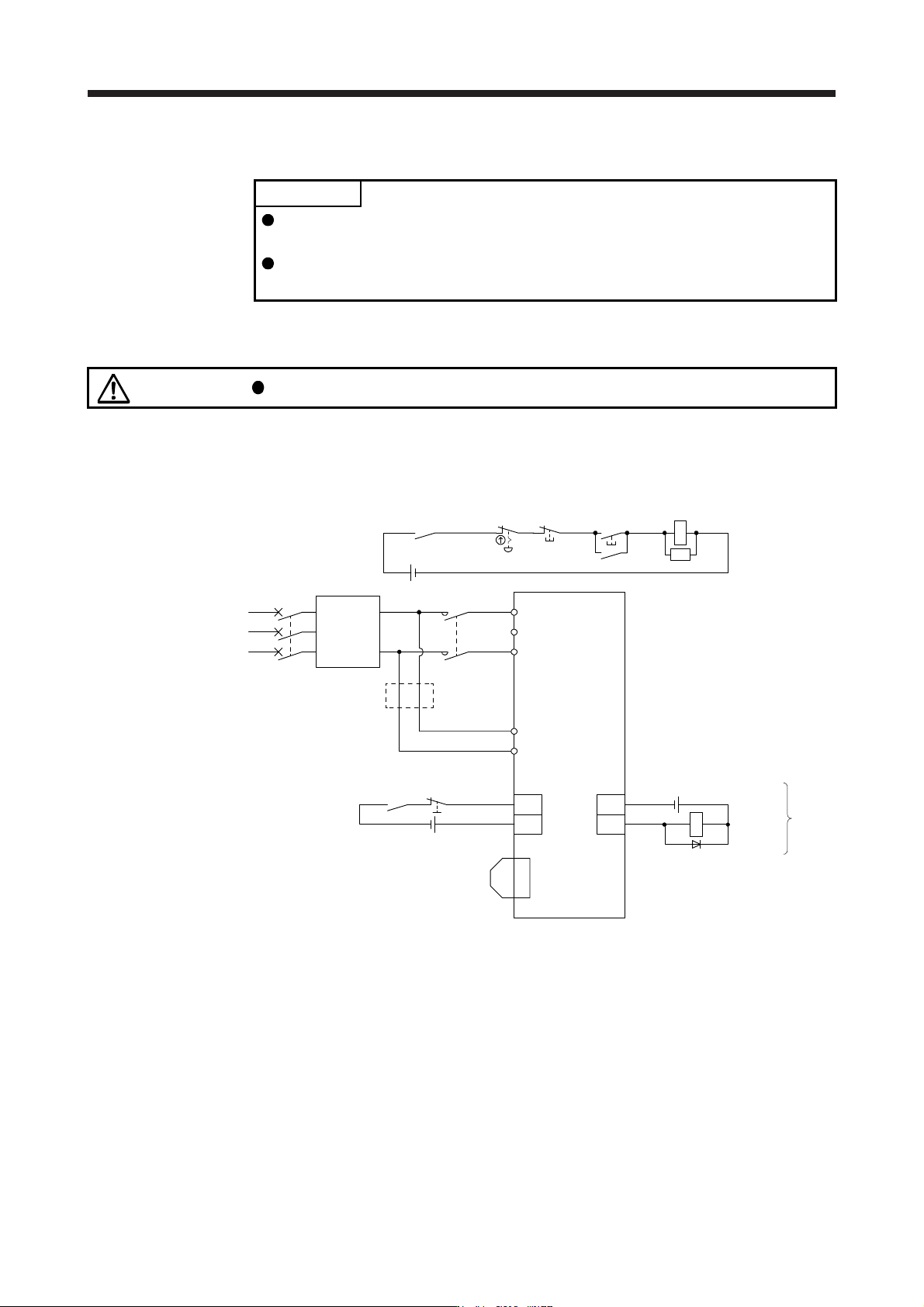
App. 15.1 Connection example
CAUTION
Ensure that polarity (+/-) is correct. Otherwise, a burst, damage, etc. may occur.
For the signal and wirings not given in this section, refer to section 3.1.1 to 3.1.3.
(1) MR-J4-10B-RJ to MR-J4-100B-RJ
(Note 2) Forced stop 2
MC (Note 3)
ALM
DOCOM
CN3
(Note 2)
24 V DC (Note 6)
24 V DC (Note 6)
24 V DC (Note 7, 8)
Malfunction
(Note 9)
RA1
L1
L2
L3
3-phase or 1-phase
200 V AC to 240 V AC
Servo amplifier
L11
L21
Malfunction
RA1
OFF
MC
ON
MC
Emergency stop switch
CN3
EM2
CN8
(Note 5)
Short-circuit connector
(packed with the servo
amplifier)
(Note 4)
Main circuit power supply
MCCB
AC/DC
Converter
(283 V DC to
340 V DC)
SK
DOCOM
(Note 10)
+
-
(Note 1)
Note 1. For the power suppl
y
specifications, refer to section 1.3.
2. This diagram shows sink I/O interface. For source I/O interface, refer to section 3.8.3.
3. Use the magnetic contactor with an operation delay time (interval between current being applied to the coil until closure of
contacts) of 80 ms or less (160 ms or less for 5 kW or more). Depending on the main circuit voltage and operation pattern, bus
voltage decreases, and that may cause the forced stop deceleration to shift to the dynamic brake deceleration. When dynamic
brake deceleration is not required, dela
y
the time to turn off the ma
g
netic contactor.
4. Configure a circuit to turn off EM2 when the main circuit power is turned off to prevent an unexpected restart of the servo
amplifier.
5. When not usin
g
the STO function, attach the short-circuit connector came with a servo amplifier.
6. The illustration of the 24 V DC power supply is divided between input signal and output signal for convenience. However, they
can be configured by one.
7. Drivin
g
the on switch and off switch with the DC power suppl
y
meets IEC/EN 60204-1 requirements.
8. Do not use the 24 V DC interface power supply for the magnetic contactor DC power supply. Always use the power supply
designed exclusively for the magnetic contactor.
9. If ALM (Malfunction) output is disabled with the parameter, configure the power supply circuit which switches off the magnetic
contactor after detection of alarm occurrence on the servo s
y
stem controlle
r
side.
10. When wires used for L11 and L21 are thinner than wires used for L1 and L3, use a fuse. (Refer to app. 15.4.)