3OM-1075-002.pdf - 第116页
*2 Fdr . No. Shown under this title are the feeder Nos. Refer to " • Operation Procedure" (described later) for the detailed information on how to add or delete feeder Nos. (Fdr . Nos.). *3 Component ID. Displa…
4.3 "Placement Feeder Location" Tab
4.3.1 "Feeder Base #1", "Feeder Base #3", and "Feeder Base #4"
Tabs
The tape feeders are allocated to Feeder Bases #1, #3, and #4.
• Sheet Layout
When the "Feeder Base #1" tab is pressed in the "Placement Feeder
Location" tab sheet, the following tab sheet appears.
Follow the same procedure to make the "Feeder Carriage #3"
or "Feeder Carriage #4" tab sheet visible.
Fig. 3B162 "Feeder Base #1" Tab Sheet (Provided with Multi-Layer Tray Feeder 2)
The tab sheet may look different, depending on which options
are selected.
• Sheet Composition
Each parameter is displayed or can be entered.
Refer to "4.1.3 Basic Usage of Text Boxes" for the detailed in-
formation on how to enter parameters.
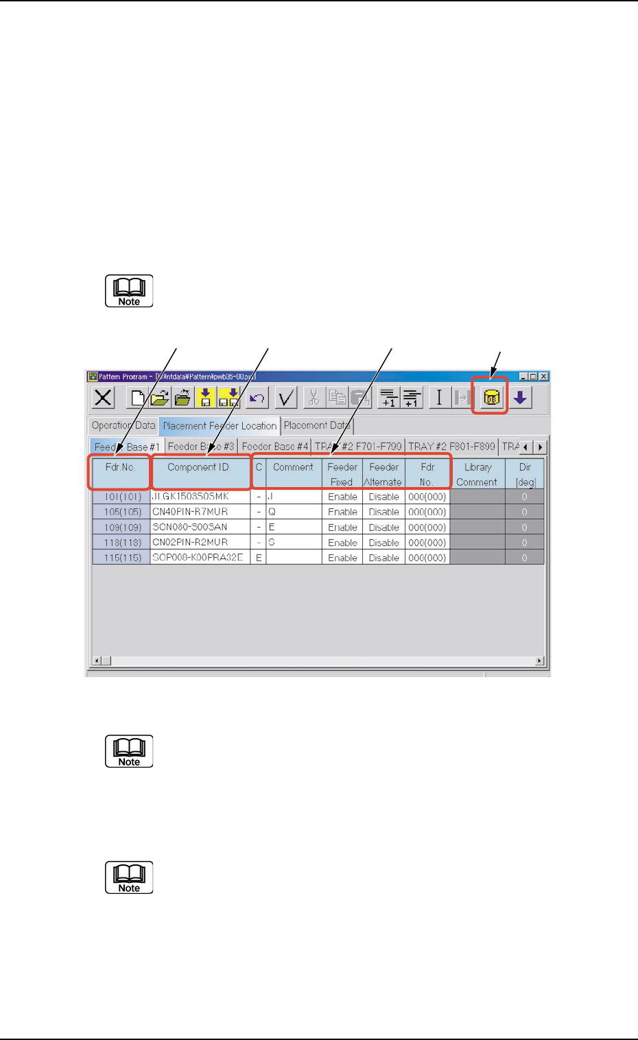
*1 [Component ID List] Icon
When this icon is pressed, the "Component ID List" window opens.
This window enables you to select a component ID from the com-
ponent library and allocate it to an arbitrary feeder (Fdr. No.).
Refer to "4.3.2 "Component ID List" Window" for details.
*1*2 *3 *4
0308-002 2-96 AHB01EDTP
4.3 "Placement Feeder Location" Tab
*2 Fdr. No.
Shown under this title are the feeder Nos.
Refer to "• Operation Procedure" (described later) for the
detailed information on how to add or delete feeder Nos.
(Fdr. Nos.).
*3 Component ID.
Displayed are the currently allocated component IDs.
Refer to "4.3.2 "Component ID List" Window" for how to
enter or delete a component ID.
*4 C, Comment, Feeder Fixed, Feeder Alternate, Fdr No.
Fig. 3B163 "Feeder Base #1" Tab Sheet (Provided with Multi-Layer Tray Feeder 2)
The tab sheet may look different, depending on which options
are selected.
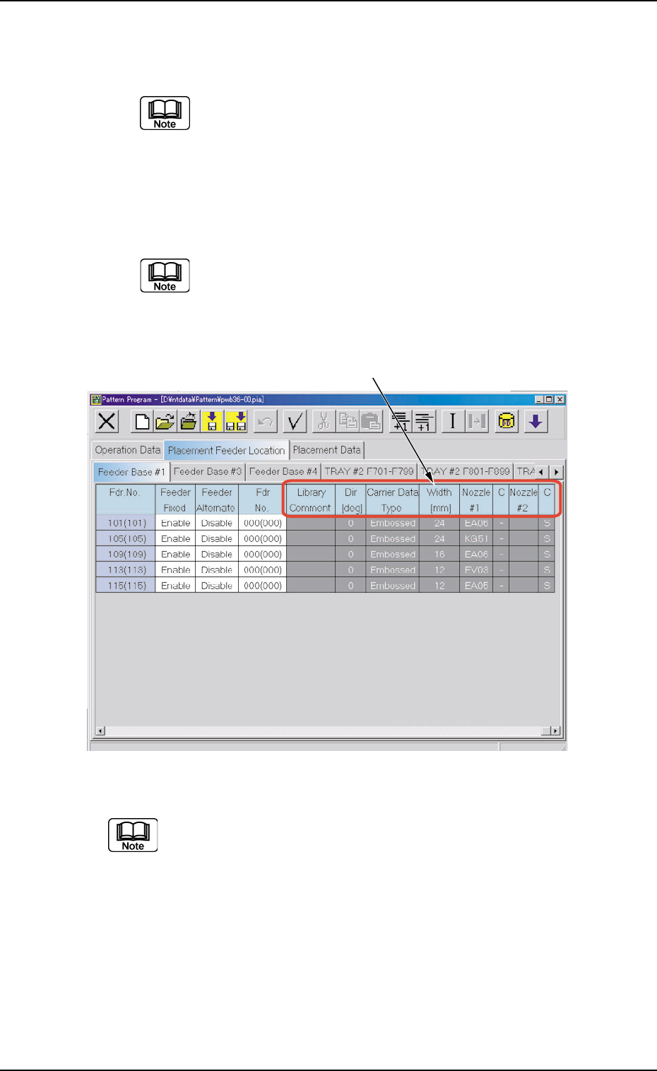
*5 Library Comment, Dir [deg], Carrier Data Type, Width [mm],
Nozzle #1, C, Nozzle #2, and C
Displayed are the parameters specified in the component library.
*5
0308-002 2-97 AHB01EDTP
4.3 "Placement Feeder Location" Tab
• Operation Procedure
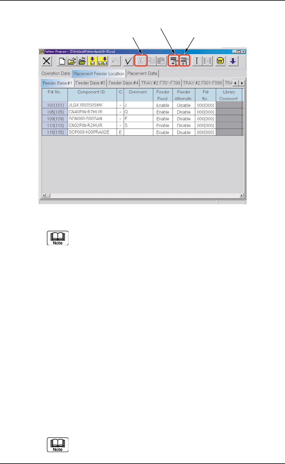
Fig. 3B164 Menus for Editing (Provided with Multi-Layer Tray Feeder 2)
The tab sheet may look different, depending on which options
are selected.
Addition of "Fdr. No."
(1) When the [Add One Line] icon is selected, a new "Fdr. No." is added
to the last line (last Fdr. No.).
Insertion of "Fdr. No."
(1) Select the position where an Fdr. No. should be inserted with the
touch screen or the pointing device.
The selected line (Fdr. No.) turns blue, indicating that it is selected.
(2) Select the [Insert One Line] icon.
A new line (Fdr. No.) is inserted at the selected line and the subse-
quent lines (Fdr. Nos.) are shifted down.
Deletion of "Fdr. No."
(1) Select the Fdr. No. to be deleted with the touch screen or the point-
ing device.
The selected line (Fdr. No.) turns blue, indicating that it is selected.
(2) Select the [Cut] icon.
The selected line (Fdr. No.) is deleted and the subsequent lines (Fdr.
Nos.) are shifted up.
Do not set any parameters for the feeder bases that are not
used. Otherwise, a data error occurs.
If parameters are set, be sure to delete them.
[Add One Line] Icon
[Cut] Icon
[Insert One Line] Icon
0308-002 2-98 AHB01EDTP
4.3 "Placement Feeder Location" Tab