3OM-1075-002.pdf - 第224页
01 12-001 4-41 AHB01EDTP (2) [A: missing sensor] Button Each text box shows the total number of component missing er- rors detected by the vacuum sensor for each individual feeders. (3) [B: missing recog] Button Each tex…
0206-002 4-40 AHB01EDTP
5.1 "Feeder Message Rate" Tab
5.1 "Feeder Message Rate" Tab
The corresponding tab sheet displays the pick-up rates (managed for
each individual feeders) based on the feeder message rates specified
in the auto operation setup data.
• Sheet Layout
When the "Feeder Message Rate" tab is pressed in the "Bypass &
Rate Data" window, the following tab sheet appears inside the win-
dow.
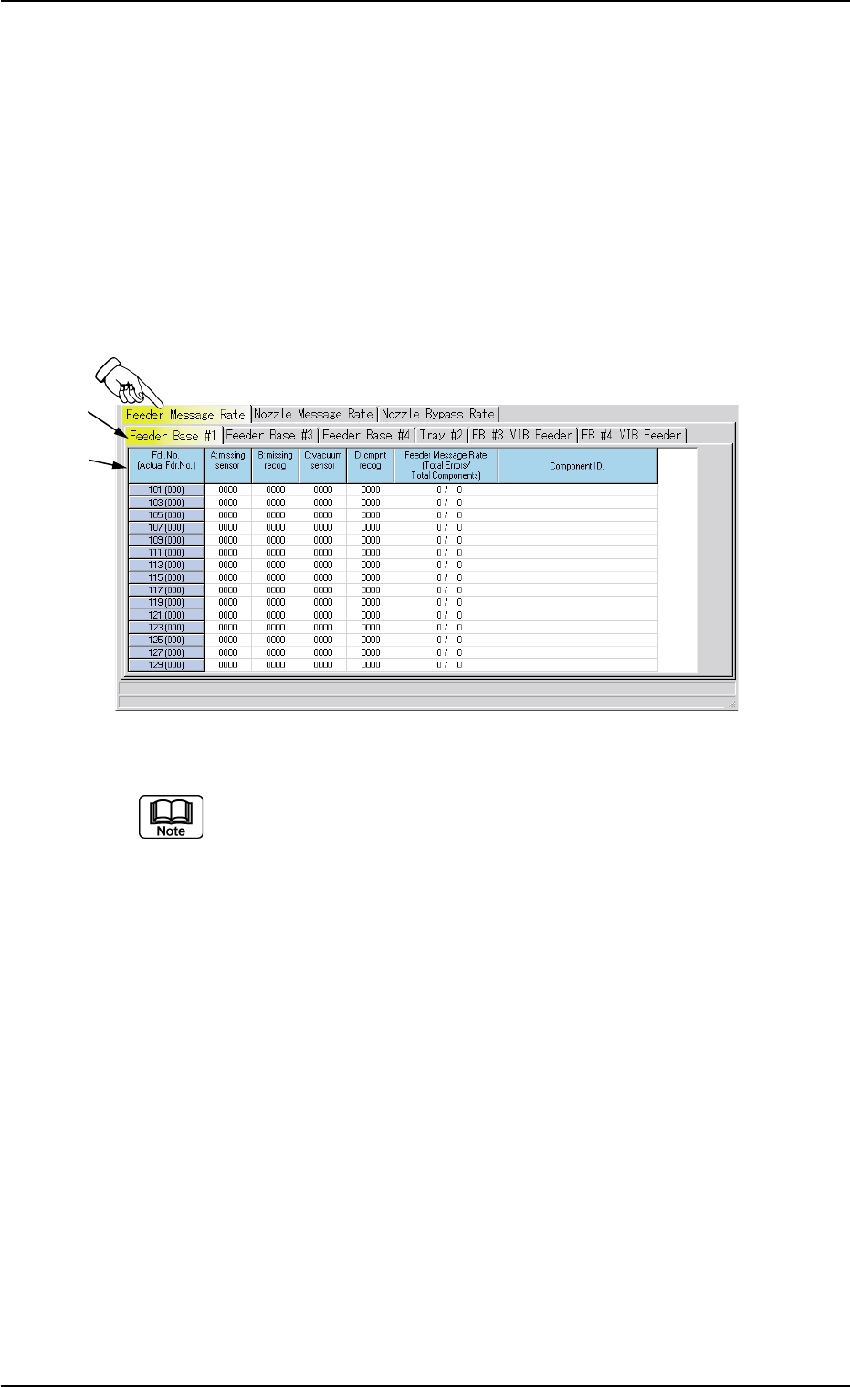
Fig. 3D21 "Feeder Message Rate" Tab Sheet
The tab sheet may look different, depending on which options
are selected.
• Sheet Composition
*1 Tabs and Tab Sheets
The "Feeder Message Rate" tab sheet is divided further into several
tab sheets and each tab sheet shows the feeder message rates on
each individual feeder bases and trays.
When a tab is pressed, the corresponding tab sheet appears, indi-
cating that the related feeder base or tray is selected.
*2 Items
The following items are displayed.
(1) [Fdr. No. (Actual Fdr No.)] Button
Shown are the feeder Nos.
*1
*2

01 12-001 4-41 AHB01EDTP
(2) [A: missing sensor] Button
Each text box shows the total number of component missing er-
rors detected by the vacuum sensor for each individual feeders.
(3) [B: missing recog] Button
Each text box shows the total number of component missing er-
rors detected through recognition operation for each individual
feeders.
(4) [C: vacuum sensor] Button
Each text box shows the total number of component pick-up er-
rors detected by the vacuum sensor (errors not detected through
the recognition operation) for each individual feeders.
(5) [D: cmpnt recog] Button
Each text box shows the total number of errors detected through
recognition operation for each individual feeders.
(6) [Feeder Message Rate (Total Errors/Total Components)]
Button
Each text box shows the rate of pick-up errors (the number of
pick-up errors per number of picked components) for each indi-
vidual feeders.
(7) [Component ID.] Button
Each text box shows the component ID for each individual feed-
ers.
5.1 "Feeder Message Rate" Tab
0206-002 4-42 AHB01EDTP
5.2 "Nozzle Message Rate" Tab
5.2 "Nozzle Message Rate" Tab
The corresponding tab sheet displays the pick-up rates (managed for
each individual nozzles) based on the nozzle message rates specified
in the auto operation setup data.
• Sheet Layout
When the "Nozzle Message Rate" tab is pressed in the "Bypass &
Rate Data" window, the following tab sheet appears inside the win-
dow.
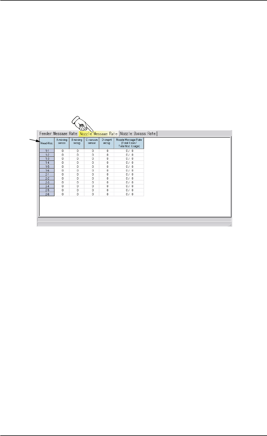
Fig. 3D22 "Nozzle Message Rate" Tab Sheet
• Sheet Composition
*1 Items
The following items are displayed.
(1) [Head-Noz.] Button
Shown are the nozzle Nos. (1 through 6) on each head No. (1 and
2).
(2) [A: missing sensor] Button
Each text box shows the number of missing components de-
tected by the vacuum sensor.
(3) [B: missing recog] Button
Each text box shows the number of missing components de-
tected through recognition processing.
*1