3OM-1075-002.pdf - 第63页
(B02_02) Component ID Set component IDs in the text boxes. (B02_03) C Set control commands in the text boxes. - (hyphen) : This command handles the steps as those for the placement feeder location data. E : This command …
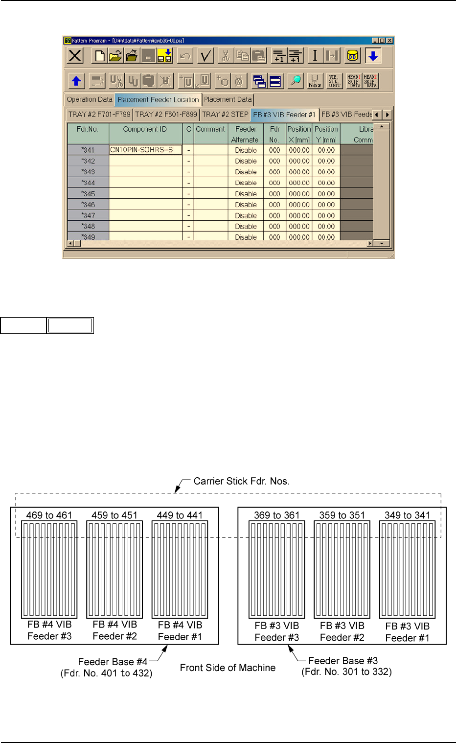
Fig. 3B76 Edit Window (Example)
(B02_01) Fdr. No.
Shown are the feeder Nos. of the carrier sticks.
Data Input Range
FB #3 VIB Feeder #1: 341 to 349
FB #3 VIB Feeder #2: 351 to 359
FB #3 VIB Feeder #3: 361 to 369
FB #4 VIB Feeder #1: 441 to 449
FB #4 VIB Feeder #2: 451 to 459
FB #4 VIB Feeder #3: 461 to 469
Fig. 3B78
2.4 Placement Feeder Location Data
0308-004 2-43 AHB01EDTP
Fig. 3B77
Fdr No.
341
(B02_02) Component ID
Set component IDs in the text boxes.
(B02_03) C
Set control commands in the text boxes.
- (hyphen) : This command handles the steps as those for
the placement feeder location data.
E : This command shows the end of the placement feeder
location data.
The step where "E" is set is valid.
S:This command invalidates the steps specified as place-
ment feeder location data.
X:This command invalidates the steps specified as place-
ment feeder location data and shows the end of the data.
(B02_04) Comment
A comment can be entered for each feeder No. (Fdr. No.).
Up to 32 characters (alphanumerics and marks) can be
used.
(a) The performance of the machine is not affected by these
commands. In other words, it has nothing to do with or
without these comments.
(b) It is recommended to set helpful information on comments
related to the feeder Nos. (Fdr. Nos.).
(B02_05) Feeder Alternate
Select "Enable" or "Disable" to determine whether or not the
feeder alternate function should be used.
Disable : The feeder alternate function is not used.
Enable : The feeder alternate function is used.
(B02_06) Fdr No.
When "Enable" is selected for the feeder alternate function,
set the destination feeder No. (Fdr No.) of the feeder that will
work in place of the feeder where a component pick-up er-
ror has occurred in succession.
2.4 Placement Feeder Location Data
0308-003 2-44 AHB01EDTP
Fig. 3B81
Comment
Fig. 3B80
C
-
Fig. 3B79
Component ID.
C1005T05B0---
Fig. 3B82
Feeder Alternate
Disable
If a control command other than the following ones is
used, the step becomes invalid.
CAUTION
Fig. 3B83
Fdr No.
000 (000)
2.4 Placement Feeder Location Data
0308-003 2-45 AHB01EDTP
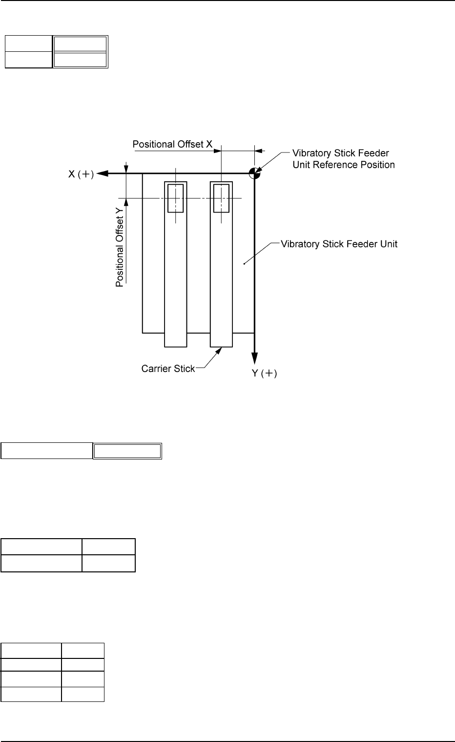
(B02_07) Position X [mm], Y [mm]
Enter the distances between the reference position of the
vibratory stick feeder unit and the pick-up position.
Unit: mm
Data Input Range
X: 0.4 to 120.0 Y: 0.4 to 50.0
Fig. 3B85
(B02_08) Library Comment
Displayed is the comment entered in the component library
data.
(B02_09) Dir [deg], Carrier Data Type
Shown are the values specified in the component library data.
(B02_10) Nozzle #1, C, Nozzle #2, C
Displayed are the nozzle IDs and control commands speci-
fied in the component library data.
X [mm]
Fig. 3B84
Y [mm]
000.00
000.00
Fig. 3B85-1
Library Comment
Fig. 3B86
Carrier Data Type
Dir [deg]
0
Vib Stick
EA06
S
EA04
-
Nozzle #1
C
Nozzle #2
C
Fig. 3B87