3OM-1075-002.pdf - 第61页
(B02) FB #3 VIB Feeder #1, #2, and #3, FB #4 VIB Feeder #1, #2, and #3 It can be determined which components must be used and which carrier stick on the vibratory stick feeders must be loaded with the selected components…
(B01_07) Fdr No.
When "Enable" is selected for the feeder alternate function,
set the destination feeder No. (Fdr No.) of the feeder that will
work in place of the feeder where component pick-up error
has occurred in succession.
(B01_08) Library Comment
Displayed is the comment entered in the component library
data.
(B01_09) Dir [deg], Carrier Data Type, Width [mm]
Shown are the values specified in the component library data.
(B01_10) Nozzle #1, C, Nozzle #2, C
Displayed are the nozzle IDs and control commands speci-
fied in the component library data.
0308-004 2-41
AHB01EDTP
2.4 Placement Feeder Location Data
Fig. 3B72
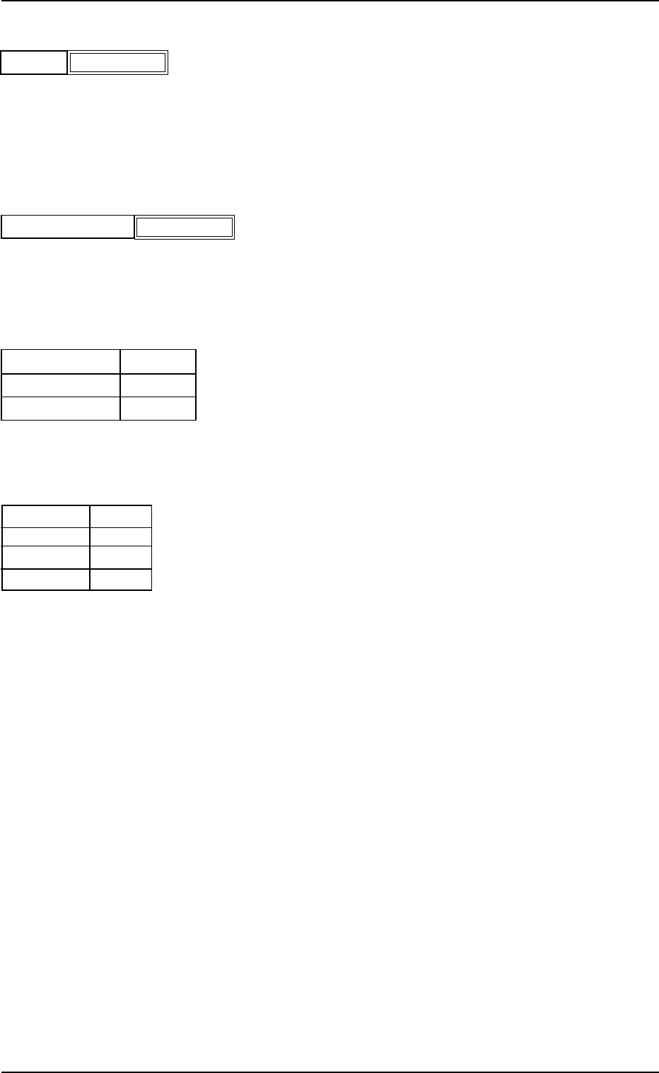
Fdr No.
000 (000)
Fig. 3B72-1
Library Comment
EA06
S
EA04
-
Nozzle #1
C
Nozzle #2
C
Fig. 3B74
Fig. 3B73
Carrier Data Type
24
Width [mm]
Dir [deg]
0
Embossed
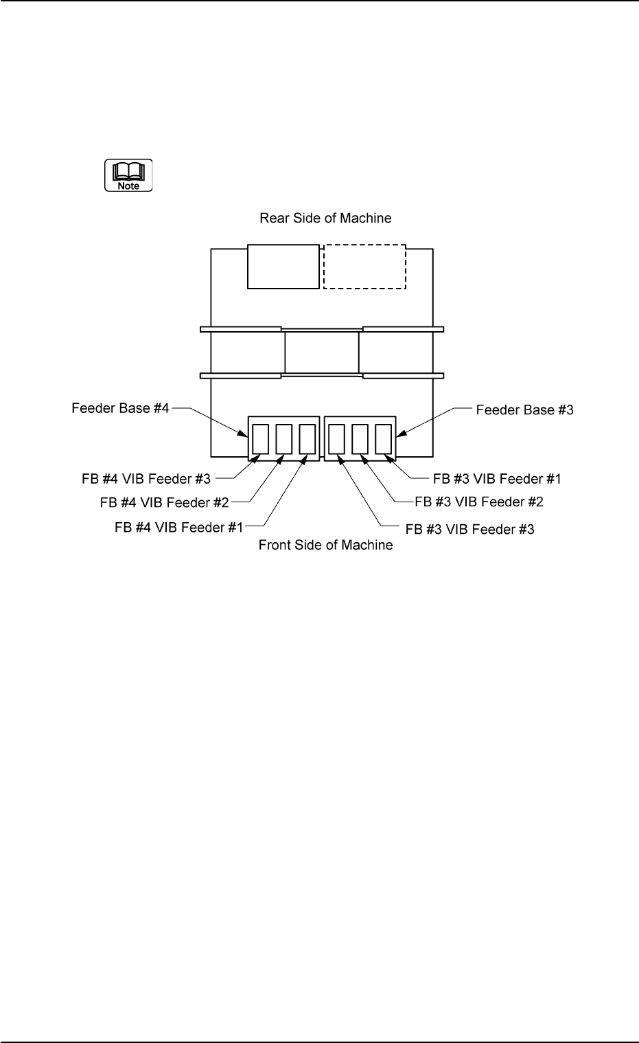
(B02) FB #3 VIB Feeder #1, #2, and #3, FB #4 VIB Feeder #1, #2,
and #3
It can be determined which components must be used and
which carrier stick on the vibratory stick feeders must be
loaded with the selected components.
(a) The following shows the positional relation between the
vibratory stick feeders.
Fig. 3B75
(b) Up to 3 vibratory feeders can be installed on one feeder
base.
(c) Up to 9 carrier sticks can be attached to one vibratory stick
feeder.
2.4 Placement Feeder Location Data
0206-003 2-42 AHB01EDTP
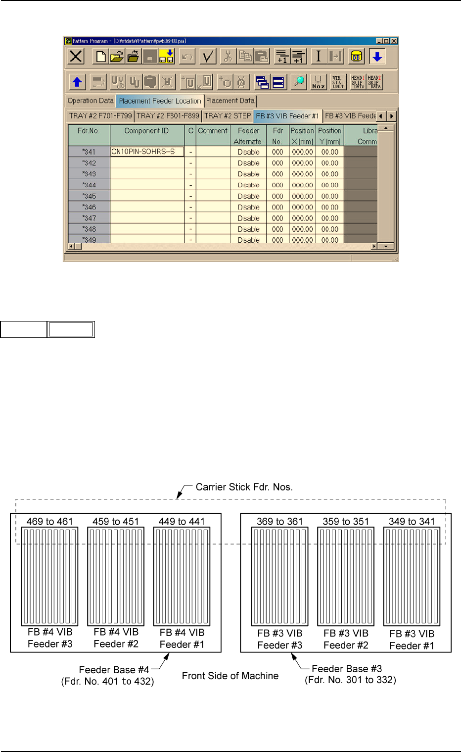
Fig. 3B76 Edit Window (Example)
(B02_01) Fdr. No.
Shown are the feeder Nos. of the carrier sticks.
Data Input Range
FB #3 VIB Feeder #1: 341 to 349
FB #3 VIB Feeder #2: 351 to 359
FB #3 VIB Feeder #3: 361 to 369
FB #4 VIB Feeder #1: 441 to 449
FB #4 VIB Feeder #2: 451 to 459
FB #4 VIB Feeder #3: 461 to 469
Fig. 3B78
2.4 Placement Feeder Location Data
0308-004 2-43 AHB01EDTP
Fig. 3B77
Fdr No.
341